|
<< Click to Display Table of Contents > USC Cards |
  
|
|
<< Click to Display Table of Contents > USC Cards |
|
The following dialog can be reached by Menu item Settings → System → Optic. The dialog allows to define the settings of the geometrical dimensions of the scanner field for the selected head:
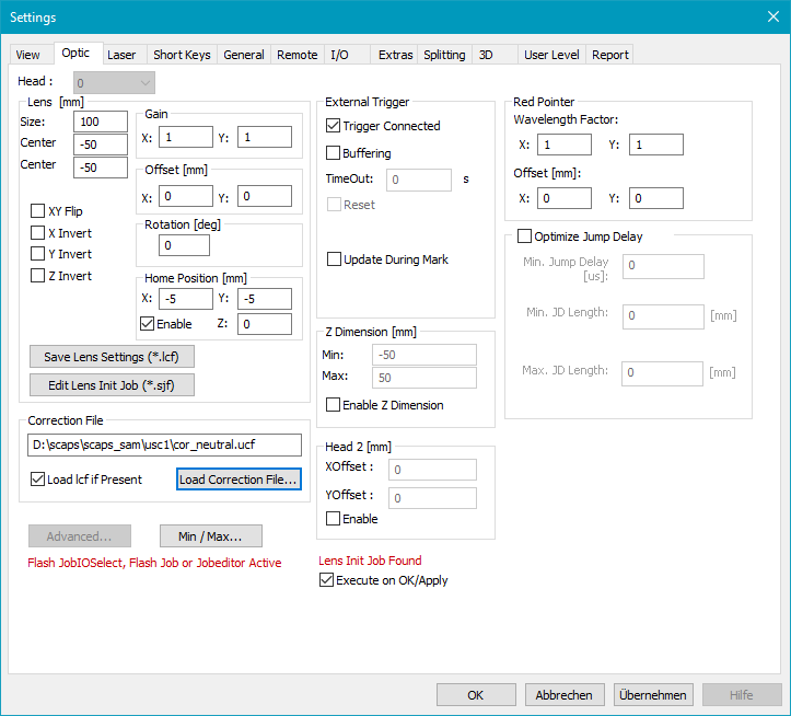
Figure 51: Optic Settings for USC cards
Head: Here the head number can be selected if more than one head is present. For this setting the software option MultiHead is required.
Lens [mm]:
Size: Specifies the maximum scanning field. This is the maximum field the scanner system can drive. In general it depends on the optical system (like lenses, etc.), the scanning distance and the maximum scanning angle of the scanner system. On 16 bit scanning systems the field extent corresponds in general to the bit values -32767 to 32767 respectively.
If the dimensions of output do not correspond to the dimensions of the drawn object, this can be corrected by changing the field size. Thereby the new field size is being calculated out of the current field size in the following way:
corrected field size = current field size * C / O
C is the current output dimension and O is the original dimension of the drawn object.
Center X, Y: Defines the center of the scanner field according to the world coordinate system.
XY Flip: Exchanges X and Y axis.
X, Y, Z Invert: Inverts the axis direction. Z Invert requires the SAM software options Optic3D or SAM3D.
Gain X, Y: The X and Y gain values are thought to compensate slightly X, Y gain errors to archive a quadratic field. Values less than 1 will reduce the scanner field. Values greater than 1 will expand the scanner field. Global gain errors which have the same deviation in X and Y directions should be corrected by changing the size of the scanner field (see above).
Example for calculating the size of the scanner field:
If for example the correction table has a step size of 550 bits/mm and the scanner has a 16 bit scanning system, the
size of the scanner field = 65535 bits * mm / 550 bits = 119.16 mm
Considering a Gain factor:
scanner field in x direction = 119.16 mm * Gain X
scanner field in y direction = 119.16 mm * Gain Y
Offset X, Y: The offset values are thought to slightly compensate X, Y offset errors to achieve the theoretical midpoint of the scanner field. Global offset errors which have the same deviation in X and Y directions should be corrected by changing the field X, Y min values in field.
Rotation [deg]: The scanner output is rotated by an angle that is entered here.
|
The Gain, Offset and Rotation values entered here will not affect the Optic Matrix. To change the Optic Matrix you have to go to Advanced → Correction → Settings. |
|---|
Home Position X, Y, Z: If this option is enabled, the home position is the position where the scanner is located when no scanning takes place i.e. during handling activity. The home position is in normal cases outside the working area but it must be inside the scanner field.
Save lens settings (*.lcf): A lens settings file stores all lens specific information. The data stored in the lens settings file include the whole parameters in the Lens field, the 4 parameters under Settings → System → Laser → Red Pointer and the Red pointer delay in Mark Dialog → Advanced. The file will be generated or updated if you click this button. The name of the *.lcf file is bound to the name of the correction file you want to use and needs to be in the same directory.
Edit Lens Init Job (*.sjf): Opens the Edit_Lens_Init_Job_Dialog. If a job should be executed every time a lens is chosen, a lens initiation job can be created. This job will be executed when switching to the corresponding correction file via this dialog. A typical job could be: waiting for an input, setting an output, executing a motion control or running an executable. The name of the lens init job (*.sjf file) must equal the name of the selected correction file and needs to be in the same directory (automatically done when using the button). When switching correction files, the message 'Lens Init Job found' indicates if an existing lens init job file for this correction file has been found. To suppress the execution of this file please disable 'Execute on OK/Apply' before clicking apply/OK. If the job should not be executed any more it can be deleted in the corresponding directory.
Correction File Settings: Here a correction file can be specified. It is used to compensate optical distortions (barrel / pincushion) of the scan head. Usually the scan head manufacturer can provide a correction file for their products. For USC cards the standard extension is .ucf. By clicking on 'Load Correction File...' a browser dialog opens. After selecting a correction file, the corresponding lens settings file (*.lcf) and lens init job (*.sjf) will be opened together with the correction file if these files are stored at the same directory. That means by using this button different lens- and correction file configurations can be managed. If you do not want to load an *.lcf file together with your correction file, you can disable 'Load lcf if present'. The checkbox is activated per default; a deactivation is only valid for the next loading of a correction file.
Advanced...: See dialog USC-1 Card Settings, USC-2 Card Settings or USC-3 Card Settings.
Flash JobIOSelect, Flash Job or Jobeditor active: Appears for USC-2 or USC-3 card if Flash Job IO Selection mode, a Flash Job or a Jobeditor license is used and deactivates the "Advanced..." button. To activate it in case of Flash Job IO Selection mode, please open Flash dialog at Menu bar → Extras → Flash an press "STOP IOSelect" button, which then turns to "START" button.
Min:/Max: Opens the Min/Max Dialog to define the range of the values speed, frequency and first pulse killer length of the laser.
External Trigger:
Trigger connected: enables the external trigger and the flags described below. This checkbox activates the "External trigger" in the Mark dialog and "Mark - Trigger".
Buffering: If in trigger mode, the job is buffered (several times) on the scanner card. This allows a faster start of the marking in response to the external trigger signal. The buffer is refilled before it is drained. In buffering trigger mode, the Status Outputs do not work. This function is only recommended if no exe or motion objects are included to the job. It can be marked, but only one job can be buffered.
TimeOut: If waiting for the trigger, the buffer on the scanner card will be cleared after there was no external trigger signal for longer than a given time. While clearing and refilling the buffer, an external trigger signal is ignored. The time out value needs to be bigger than the time for marking.
Reset: If this option is enabled it extends the timeout operation. In this case not only the buffer of the scanner card is cleared but the sequence is reset too. That means when a timeout occurs and this checkbox is selected all serial numbers are reset to their defined starting values automatically.
Don't update view during mark trigger: If this option is enabled the view will not be updated when using Mark → Trigger as long as the Mark Trigger window is active.
Update during mark: If this checkbox is active, the next sequence is set within the current job before it ends. This means that serial numbers are for example incremented or re-split. This checkbox is only valid if "Next sequence before mark" is unchecked.
MultiHead Independent: It only effects on the trigger mode. This allows to trigger the scan heads independently from each other when the Mark→Trigger dialog is used. This might be useful if one of the scan heads has to mark for example 5 objects while the other scan head will only mark one object at the same time. This function will not work together with serial number objects nor with DateTime objects. Status output Marking In Progress (MIP) remains active after the first marking.
Red pointer:
Wavelength Factor: Correction for the red pointer in X and Y direction caused by different wavelength of the laser. The factor is determined experimentally. When marking one reference point with the red pointer and the laser, the vector length R from center to the point marked with the red pointer and the vector length L from center to the point marked with the laser needs to be measured in x and y direction. Wavelength Factor = Red pointer / Laser.
Offset: Static X/Y offset correction only for the red pointer caused by the different wavelengths of the laser. The factor is determined experimentally (see Wavelength Factor).
Z Dimension: This requires the software option Optic3D.
|
Optic settings can be changed in the optic settings dialog which can be reached by Menu item Settings → System → Optic, but there is also an other way: |
|---|
1.Close all SAM based applications (Check this with task-manager).
2.Start sc_setup.exe from folder <SCAPS>\tools\
3.Click on Menu Hardware Settings → Settings
Head 2 (not available for USC-1):
X, Y Offset: Define an offset for the second scan head. If everything is set to 0 then the second scan head will mark on the same position as the first head is marking.
Enable: Activate this checkbox to enable the usage of the second scan head.
|
If the MultiHead option is used, then the Head 2 options are disabled. Instead there is an additional option in the External Trigger options: MultiHead Independent. Therefore see Optic Settings Dialog USC-1. |
|---|
Lens Init Job found: Appears if a correction file is loaded and an appropriate Lens Init Job is available.
