|
<< Click to Display Table of Contents > USC-3 Settings |
  
|
|
<< Click to Display Table of Contents > USC-3 Settings |
|
Card Settings for USC-3 card. This dialog can also be opened when SAMLight is running: Menu bar → Settings → System → Optic → Advanced...:
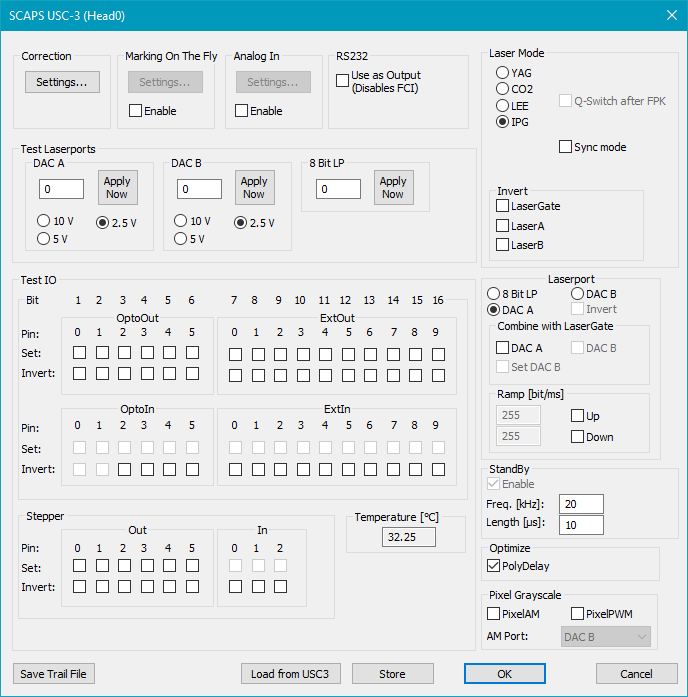
Figure 26: Card Settings for USC-3 Card
Correction:
Settings...: Click this button to open the Correction File Dialog for the USC-3 card. See chapter USC-3 correction settings.
Marking On The Fly (MOTF): Requires the Marking On The Fly (MOTF) SAMLight option.
Settings...: See chapter Card Specific: USC-3.
Enable: Check this to enable MOTF.
Analog In:
Settings...: There an Analog Input signal can be used that affects the scanner position. See chapter Analog In.
Enable: Check this to enable Analog In.
RS232:
Use as Output (disables FCI): Activates RS232 as Output for controlling laser and motion controller, therefore Flash Control Interface (FCI) to send Flash commands by RS232 is disabled.
Test Laserports:
DAC A/B: Here you can test the Digital Output A/B. This can be observed with a DB-37 Diagnostic Board attached to the USC-3 card. The minimum value for the digital output is 0, the maximum is 4095. Value is also set after reboot (if stored) or with the start of SAMLight. For 10V, the full 12 bit resolution is used, for 5V, the values are shifted 1 bit, for 2.5V 2 bit to the right (down).
8 Bit LP: Here you can test the 8 bit laserport by entering a value from 0 to 255. This can be observed with a DB-37 Diagnostic Board connected to the USC-3 card.
Test IO:
OptoOut/In: Here you can test if the bits of Opto_Out and Opto_In can be set correctly.
ExtOut/In: Here you can test the additional I/O bits. These I/Os can be used for Job IO Selection mode or to control external devices.
Stepper:
Out/In: If connected test the I/Os of a stepper motor.
Laser Mode: Here you can choose the type of the laser (YAG, CO2, LEE, IPG ). Standard timing diagrams of laser signals are given here.
Q-Switch after FPK: Sets the Q-Switch after the first pulse killer.
LaserB as FPK: Only visible for CO2 Laser. Enables the First Pulse setting at pen settings main.
IPG sync mode: Only visible for IPG Laser. Restart the Laser_A signal with a defined delay before the opening of the Laser_Gate signal. This option enables synchronized Laser_A signal with rising edge of the Laser_Gate.
ParaDel. [ms]: This field is only available for laser modes 588-1 and 588-2. The value causes the software to wait after a pulse width change (special laser parameter) had been sent to the interface. The unit of the entered value is [ms].
PreFreq. [ms]: This field is only available for laser mode 723. The value causes the software to wait after a change of the pen frequency for the laser to adapt. This means that the value given here (in ms) is the minimum time delay between a pen change and the start of the next marking sequence.
Invert: Laser Gate, Laser A, Laser B: Here the laser signals can be set to be active low or active high.
|
For security reasons, the USC-3 Laser signals can only be changed with <SCAPS>\tools\sc_setup.exe → HardwareSettings, "choose settings file" → Settings → Driver Settings, not in SAMLight. |
|---|
Laserport: Defines the port that sends the power signal for the laser (8 Bit LP, DAC A, DAC B).
Invert: Shows the status of the Laserport. Just for "LEE" Laser Mode the 8 Bit LP is inverted.
Combine with Laser_Gate: If DAC A or DAC B is chosen under Laserport it is possible to turn off the laser power signal with the Laser_Gate. If Laser_Gate is going down DAC A or DAC B will also go down to 0. If the checkbox Set DAC B is activated the DAC A will not go to 0 when Laser_Gate is going down but it will be set to the value that is defined under Test Laser ports → DAC B.
Ramp: Defines the velocity of the increasing or decreasing of the power of the laser port.
Enable: Globally enables standby mode.
Freq.: Q-Switch frequency of the laser pulses.
Length: Q-Switch length in µs.
AlwaysActive: Standby mode is also used when the laser signal is on.
Optimize:
PolyDelay: If this is selected the length of the polygon delay gets varied depending on the angle between two successive vectors.
Pixel Grayscale:
PixelAM: Enables Amplitude Modulation.
PixelPWM: Enables Pulse Width Modulation. For more details see chapter Pulse Modulation.
AM Port: Select the output of the bitmap grayscale amplitude modulation. PixelAM must be enabled.
•DAC B: The 12 bit analog port DAC_B on the Laser, I/O - 37 pin connector.
•Laserport: The laser port selected from above.
•Digital Out: From Digi_Out_0 (LSB) to Digi_Out_9 (MSB) on the Extension - 40 pin connector. This only works in Gray Advanced mode and does not work in flash (standalone mode), yet.
Save Trail File: Saves the USC-3 trail file to <SCAPS>\intermed\. The file name corresponds to sc_usc3_trail_head_x.txt, where x stands for the head number.
Store: Stores the settings to the USC-3 (this is necessary for stand-alone operation). Make sure that the settings fit to the laser and other machinery. The settings will be loaded during powering on the card.
Load from USC3: Load the settings from USC-3 into SAMLight. Only a subset containing the following information is loaded:
•All settings made in the sc_setup.exe at Hardware Settings → Settings
•Pen Settings without Ramping and the function Mark Lines as Dots
