|
<< Click to Display Table of Contents > I/O |
  
|
|
<< Click to Display Table of Contents > I/O |
|
The settings dialog described here can be reached by selecting the menu item Settings → System → I/O.
Use this window to set special inputs and outputs or to make settings for the SAMLight Job IO Selection mode.
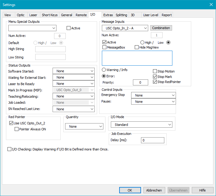
Figure 66: IO Settings Dialog
Menu Special Outputs: It is possible to insert new menu items for switching I/Os on and off. The bits of the I/O port which will be controlled from special menu points can be defined in the dialog. If one bit is selected and the Active checkbox is enabled a string (Num Active) which indicates the current state of the bit can be defined. Under the following menu the items for switching the I/Os on and off will be inserted.
![]()
Figure 67: Mark Special Outputs Menu
Default: Defines the default state of the special output that is shown in the menu.
High String: Defines the String that is shown when the special output is set to Low.
Low String: Defines the String that is shown when the special output is set to High.
Status Outputs: This block defines state I/Os that can be switched on an off according to specific program and usage actions. Using the combo boxes it is possible to assign a special output pin for such an action. Using this functionality an integration of external equipment can be done.
Software started: The selected bit is set to high as long as the software is running.
Waiting for external start: Set to high if in trigger mode. This changes to low during marking.
Laser to be ready: Set to high if trigger or mark dialog is open. This stays high during marking.
Marking active: Set to high during marking of a job. Only for USC cards this signal is hardware controlled. For RTC cards this signal is software polled with the result of jitter. For proper I/O handling, this signal has to be used, not the RTC busyout.
Teaching / Relocating: If an output pin is defined here it is set to high on every time the teaching or relocating dialog is active.
Job loaded: The selected bit is set to high if a non empty job is loaded in the View.
SN reached last line: If a file is assigned to a serial id and the last line of this file has been reached this bit is set. To change the state afterwards you have to reset the serial id or load a new job. Instead or in addition you can pop up a message box if the last line of the file has been marked.
Red Pointer:
Use Bit 3: Bit 3 of the I/O port is used to indicate that the red pointer is active.
Pointer always ON: The Red Pointer stays always on (while SAMLight is running) if this flag is activated.
Invert: This option is only available for RTC cards and USC-1. It inverts bit 3 for controlling the red pointer.
Quantity: Here an output can be defined that goes high when a predefined number of mark quantities has been reached. The predefined number of mark quantities can be set up in Mark→Counter→Set Quantities.
Message Inputs: Input bits can be used to cause a message output. The selected bit must be activated to send the defined message by the Active check box. The message appears if the selected bit is either high (H) or low (L) according to the selected radio button. An error or a warning message is displayed in the message view dialog as well as in the status bar. If Hide MsgView is activated, the message view is invisible.
Stop Motion: If Message Input is executed the Motion is stopped. Does not influence any homing during startup. (only available for USC-3)
Stop Mark: If Message Input is executed the Marking is stopped.
Stop RedPointer: If Message Input is executed the red pointer is stopped.
Priority: For each activated input (Warning/Info and Error), a priority can be set. If more than one input is active at the same time, the one with the highest priority will be shown in the status bar. Error always wins over Warning/Info.
•RTC input bits:
o0 .. 15 (Extension 1 connector, Digital_In 0 .. 15)
•USC input bits:
o3 .. 6 (37-pin connector, Opto_In2 .. 5)
•USC-2/3 additions:
o7 .. 16 (Extension connector, Digi_In0 .. 9)
oStatus #0 .. #19: These status bits refer to the 20-bit word of the XY2-100 feedback from the scan head. The user may define a unique message / error for any of these bits.
oError warning info: These warnings can be reset in the status bar.
▪Out of data with laser on (OD) is set when a buffer underrun occurred.
▪Out of field (OF) is set when a position overflow (head specific optic matrix, MOTF, Analog In, USC-3 Wobble) occurred.
▪Overflow MOTF offset (OM) is set when a MOTF offset is reached too early (e.g. still marking).
![]()
Figure 68: Reset OF, OD and OM by right-click followed by a left-click on Reset Warning
Num active: Counts the number of activated Message Inputs.
Combination: This button opens a dialog Message Input Combination, which can be used to combine two or three input bits.
Control Inputs:
Emergency Stop: If an input is selected here it is handled as a watch for an emergency stop condition. That means if the selected input goes to low all marking operations are stopped and a special emergency stop dialog is displayed. This dialog blocks all other operations and stays in front of the screen until normal operation is resumed by pressing the "Resume Operation" button. This button becomes active and can be pressed only after the selected emergency stop input goes to high. When the resume button is pressed the application is brought back into its initial state. That means the connected motion controllers are driven to their home position automatically before the emergency stop dialog disappears and before a user can continue with normal operation.
|
It is recommended to connect the appropriate input pin before this option is enabled. An open input normally is recognized as a low-signal so that leaving the I/O settings dialog would put the application in the emergency stop state immediately. |
|---|
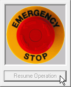
Figure 69: Emergency Stop
Pause: This functionality is only available with an USC-2 or an USC-3 card. Here you can select an input bit to pause the job. The laser is switched off immediately. After the restart, the job continues at the same position, the laser will turn on again after the next mark command, after a PolyEnd or after a jump command. Axis movement will not be paused.
I/O Mode: There are four SAMLight I/O modes (which differ from the Flash JobIOSelection mode) that can be chosen:
•Standard: the settings described above can be made including the freely definable Message Inputs.
•SAMLight JobIOSelect: SAMLight Job IO Selection mode. Opto_In_2 (LSB) .. Opto_In_5 (MSB) are used to load jobs (up to 15 jobs).
•SAMLight JobIOSelect Ext: SAMLight Job IO Selection mode. Digi_In_0 (LSB) .. Digi_In_7 (MSB) are used to load jobs (up to 255 jobs) (USC-2/-3 only).
•SAMLight JobIOSelect Ext 10 Bit: SAMLight Job IO Selection mode. Digi_In_0 (LSB) .. Digi_In_9 (MSB) are used to load jobs (up to 1024 jobs) (USC-2/-3 only).
For more information see SAMLight Job IO Selection.
|
Message inputs can also be used in Job IO Selection mode. These must be set and activated in standard mode. In Job IO Selection mode it can happen that the input loads a job as well as being defined as a message input. |
|---|
Job Execution:
Delay [ms]: Defines an execution delay which is the time between a mark output signal is given and the execution. Only for USC cards the marking active signal is hardware controlled. For RTC cards the marking active signal is software polled with the result of jitter.
USC cards:
Table 11: I/O bit values for USC cards |
RTC cards:
Table 12: I/O bit value for RTC cards |
|||||||||||||||||||||||||||||||||||||||||||||||||||||||||||||||||||||||||||||||||||||||||||||||||||||||||||||||||||||||||||||||||||||
|---|---|---|---|---|---|---|---|---|---|---|---|---|---|---|---|---|---|---|---|---|---|---|---|---|---|---|---|---|---|---|---|---|---|---|---|---|---|---|---|---|---|---|---|---|---|---|---|---|---|---|---|---|---|---|---|---|---|---|---|---|---|---|---|---|---|---|---|---|---|---|---|---|---|---|---|---|---|---|---|---|---|---|---|---|---|---|---|---|---|---|---|---|---|---|---|---|---|---|---|---|---|---|---|---|---|---|---|---|---|---|---|---|---|---|---|---|---|---|---|---|---|---|---|---|---|---|---|---|---|---|---|---|---|---|
[a]: Reserved for trigger start
[b]: Reserved for external stop
[c]: Reserved for marking active
[d]: Only reserved for the red pointer, if the red pointer is active
