|
<< Click to Display Table of Contents > USC-1 Settings |
  
|
|
<< Click to Display Table of Contents > USC-1 Settings |
|
Card Settings for USC-1 card. This dialog can also be opened when SAMLight is running: Menu bar → Settings → System → Optic → Advanced...:
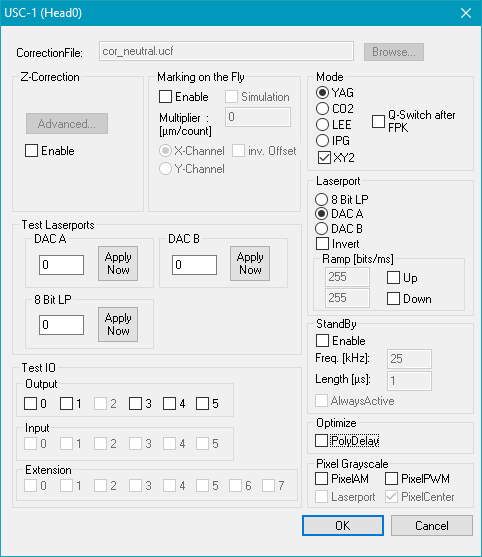
Figure 24: Card Settings for USC-1 Card
CorrectionFile: Click on the Browse button to select the correct correction file for this card.
MarkingOnTheFly: Requires the Marking On The Fly (MOTF) SAMLight option. MOTF related parameters are described in chapter Card Specific: USC-1.
Test Laserports:
DAC A/B: Here you can test the Digital Output A/B. This can be observed with a DB-37 Diagnostic Board attached to the USC-1 card. The minimum value for the digital output is 0, the maximum is 255. Value is also set after reboot (if stored) or with the start of SAMLight.
8 Bit LP: Example: If 5 is entered and Apply Now is pressed, the first and the third bit of the digital port are high.
Test IO: The IO-Port is a 6-bit port. For the USC-1 scanner card the first output bit is predefined for marking in progress. The first input bit is predefined for external start, the second for stop.
Mode: Here you can choose the type of the laser (YAG, CO2, LEE, IPG ). Standard timing diagrams of laser signals are given here.
XY2: Defines that the scanner driver signals are standard XY2-100
ParaDel. [ms]: This field is only available for laser modes 588-1 and 588-2. The value causes the software to wait after a pulse width change had been sent to the interface. The unit of the entered value is [ms].
Sync mode: Only visible for some Laser Types. Restart the Laser_A signal with a defined delay before the opening of the Laser_Gate signal. This option enables synchronized Laser_A signal with rising edge of the Laser_Gate.
|
Make sure that the 'XY2' check box is checked if not mentioned differently. |
|---|
Q-Switch after FPK: Sets Q-Switch after the first pulse killer.
Laserport: Defines the port that sends the power signal for the laser (8 Bit LP, DAC A, DAC B).
Invert: Here the laser power value can be inverted. Note: In case of 8 Bit LP this checkbox does not invert the bits.
Ramp: Here you can define a velocity to increase or decrease the power of the laser port.
Enable: Globally enables standby mode.
Freq.: Q-Switch frequency of the laser pulses.
Length: Q-Switch length in µs.
AlwaysActive: Standby mode is also used when the laser signal is on.
The settings are done after leaving the global dialog Settings. Standby Settings for pens overwrite these settings if enabled for a pen as soon as this pen is used.
Optimize:
PolyDelay: If this is selected the length of the polygon delay gets varied depending on the angle between two successive vectors.
Pixel Grayscale:
PixelAM: Enables Amplitude Modulation.
PixelPWM: Enables Pulse Width Modulation. For more details see chapter Pulse Modulation.
Laserport: If checked the selected Laserport gets used for the output of PixelAM, else port DAC B is taken.
