|
<< Click to Display Table of Contents > Splitting |
  
|
|
<< Click to Display Table of Contents > Splitting |
|
This option allows you to split a job into pieces and then mark them part by part. That automatic split marking is useful e.g. for marking round objects or objects that are bigger than the working area. Jobs are always split completely as long as there are no entities marked as non-splittable.
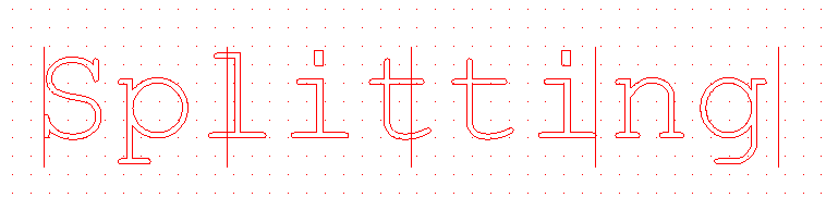
Figure 330: Example of a split job
The Splitting Dialogs can be reached via the Extras Toolbar or by selecting the appropriate menu item. If the extra toolbar is not visible, it can be activated at System → Settings → View → Toolbars → Extras.
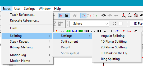
Figure 331: Splitting modes
•Vector Marking - Fixed Split Size •Vector Marking - Entity Based Splitting •Vector Marking - Character Based Splitting |
|
•Vector Marking - Fixed Split Size •Vector Marking - Entity Based Splitting •Vector Marking - Character Based Splitting |
|
•Vector Marking - Fixed Split Size •Vector Marking - Entity Based Splitting |
|
•Vector Marking - Fixed Split Size •Vector Marking - Entity Based Splitting •Bitmap marking |
|
•Vector Marking - Fixed Split Size •Vector Marking - Entity Based Splitting •Vector Marking - Character Based Splitting •Bitmap marking |
Table 48: Splitting modes and options
You can save the splitting settings within the job file. Please refer to the Job Properties Topic for more information.
Rotational marking (Angular Splitting mode) can be done by performing the following steps:
•Enable external motion control to perform the automatic rotation of the round object that has to be marked.
•Define the diameter of the object.
•Define a rotational angle that describes the segment that should be marked at the same time.
•Define the motion controller axis that has to be used for the rotation movements. That axis only defines the drive that has to be used for the motion, it does not influence the axis the job is split for.
•Turn on the splitting mode to enable the current job for rotational marking.
For planar marking (Planar Splitting modes), the following steps are necessary:
•Enable external motion control to perform the automatic movement of the flat object that has to be marked.
•Define the size of a split part that has to be marked at the same time.
•Define the motion controllers axis that has to be used for the planar movements. This axis only defines the drive that has to be used for the motion. It does not influence the axis the job is split for.
•Turn on the splitting mode to enable the current job for marking it part by part.
For Mark on the Fly of split parts, the following steps are necessary:
•You need a Marking on The Fly featured license of the SAM software.
•Define the size of one split part that has to be marked on the fly.
•Turn on the splitting mode to enable the current job for marking it part by part.
The Motion Control for the first two modes can be activated at Menu Bar → Settings → System → Extras → Motion Control. Additionally, the motion control configuration file has to be configured for the used controller as described in motion control .
|
If all of the Rotation Axis or Motion Axis radio buttons are disabled, there is a misconfiguration with the motion controller and the application will be unable to perform the correct rotational or planar movements. |
|---|
To activate splitting mode go to Extras → Splitting → Split current or use the related icons in the Extras Toolbar . This mode can be turned off by clicking on this menu button again. Then the job is restored to non-split mode.
When the splitting of a job was successful, its appearance in the View 2D is changed. Now there are several additional lines. They are the cutting edges that have been created according to the values Total Diameter and Splitting Angle (in angular mode) or Splitting Size (in planar mode). These splitting lines can be changed to optimize the result. Click on such a line and enter the object level 2 using the level toolbar. Now you can select a single splitting line. To move such a line, click on the small blue box and then drag it in the desired direction. This functionality is identical to that of the normal geometries, with the sole exception that a rotation or scaling of the splits is not possible.
|
When such a line is moved beyond one of the neighbouring cutting lines, it is automatically forced to a position back within its two neighbours. Interleaving the cuts that are represented by these lines is an invalid operation. If there are parts of the job that are located outside of the outer cutting lines after editing, they will not be marked. |
|---|
After dragging a cutting line to a new position, the split job is recalculated automatically. This operation may require some seconds, depending on the complexity of the job. Marking such a job can be done like before. Here, all the split parts are marked one by one until the complete job is done. Editing the cutting lines resets the current marking position so that the next marking operation starts with the first segment of that job.
Under Extras → Splitting → Show split(s) you can get a preview of all the created split parts.
|
To get the correct marking result, it is very important that the axes of the motors correspond to the axes of the split job. Normally, they should both form a right handed coordinate system. |
|---|
|
•If a motor movement is desired, that is independent of the splitting, all motion control objects have to be defined as non-splittable entity, see chapter Entity List. •For the correct Red pointer function in the splitting mode, you have to make settings for Split Red Pointer repetitions in the Mark Dialog --> Advanced... |
|---|

