|
<< Click to Display Table of Contents > RTC-4 Settings |
  
|
|
<< Click to Display Table of Contents > RTC-4 Settings |
|
Card Settings for RTC-4 card. This dialog can also be opened when SAMLight is running: Menu bar → Settings → System → Card → Advanced...
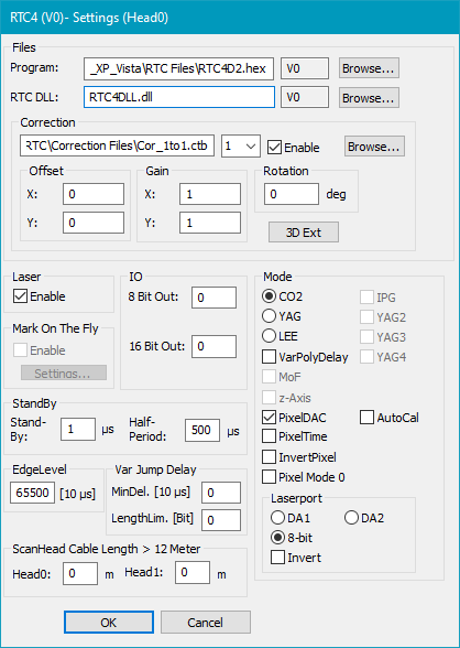
Figure 29: Card Settings for RTC4 Card
Files:
Program: Specifies the program file. This file is delivered together with the scanner card. The standard extension is *.hex. Click on the Browse button to make a search on the files location or type in the file name into the edit window.
RTC DLL: Specifies the *.dll file. This file is delivered together with the scanner controller card.
|
Using a 64-bit operating system you should nevertheless load a 32-bit RTC DLL, not the 64-bit one. |
|---|
Correction: Specifies the location of the correction file. This file is delivered together with the scanner card. The standard extension is *.ctb. Click on Browse button to make a search on the files location or type in the file name into the edit window. It is possible to load two different correction files. This is mainly used in connection with the secondary head feature of the RTC4.
Offset, Gain, Rotation: Allow a global adjustment for each correction file. These features are mainly used to adjust the fields of both heads when a secondary head is used. See also: Chapter Optic Settings Dialog.
3D Ext: Opens a dialog, where a Z-Table can be defined. For detailed information have a look at the RTC4 manual. See chapter Optic3D for RTC cards.
Laser: Globally enables or disables laser output.
Mark on Fly: Requires the Marking On The Fly RTC option. MOTF related parameters are described in chapter Card Specific: RTC cards.
StandBy: Globally enables standby mode.
Stand-by: Q-Switch length in µs for stand-by modus. If this is set to zero the stand-by mode is switched off.
Half-period: Half of the laser pulse period for stand-by modus.
|
Settings are done after leaving the global dialog Settings. Standby Settings for pens will overwrite these settings if enabled for a pen as soon as this pen is used. Also please remind that after marking has finished the settings from the Home Jump Style Pen are used. |
|---|
ScanHead cable length > 12 Meter: Put in the cable length of each head if one cable is longer than 12m.
EdgeLevel: The variable Polygon Delay gets very high if the angle of two successive vectors is close to 180° . This can lead to burn in effects. To prevent this an EdgeLevel value can be defined. If the Polygon Delay between two mark commands is greater than this value the RTC4 card switches off the laser after the first command and after the laser-off delay is over. Then a new polygon marking with the second vector will be started.
Var Jump Delay: Normally after a jump command a constant jump delay is inserted. But for very small jumps it is not necessary to have such a long jump delay. The jump delay can be reduced without loosing marking quality. The minimum delay is the delay for a jump of length 0.
IO:
Lamp/8-bit: Sets the 8 bit or one of the digital outputs of the RTC Card during start up (as selected under Laserport). The 8 bit Output corresponds to the write_8bit_port command of the RTC.
16 BIT Out: Sets the 16 bit output of the RTC Card during start up.
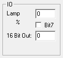
Figure 30: If LEE Mode is selected, the eighth bit is selectable separately
Mode: Here you can choose the type of the laser.
YAG2, YAG3 and YAG4: YAG4 corresponds to Laser Mode 4 like described in the SCANLAB RTC manual - YAG2 and YAG3 respectively.
VarPolyDelay: If checked the length of the polygon delay gets varied depending on the angle between two successive vectors.
MoF: Shows whether the scanner card is able to do Marking On The Fly or not.
z-Axis: Indicates whether the card is able to do 3D Marking or not.
PixelDAC: Enables Amplitude Modulation.
PixelTime: Enables Pulse Width Modulation. For more details see chapter Pulse Modulation.
InvertPixel: Inverts bitmap pixels.
Pixel Mode 0: See chapter Pixelmode.
AutoCal: Displays the ScAutoCalib button within the functionality object toolbar to generate AutoCalib control objects in the entity list, see section AutoCal Control Object.
Laserport: Defines the port that sends the power signal for the laser if the laser is not a CO2 Laser. For a CO2 Laser the power signal is done by modulating the Laser A signal.
Invert: Here the laser power value can be inverted. Note: In case of 8-bit this checkbox does not invert the bits.
|
The RTC PCI Board does not support power saving modes, that switch off power to the PCI bus. This could lead to PC freezes at the start of SAMLight. Accordingly, you must disable standby or sleep modes of the operating system and via the „SleepMode.cmd“ script, which you can find in your RTC tools folder. Please refer to your RTC manual for more information.
|
|---|

