|
<< Click to Display Table of Contents > Pulse Modulation |
  
|
|
<< Click to Display Table of Contents > Pulse Modulation |
|
Two modes are provided by the USC-1 and RTC3 to modulate the laser. In general terms they can be described as:
a) Pulse Width Modulation (PWM)
b) Amplitude modulation (AM)
In PWM mode the LaserON Signal is modulated. In AM mode the analog output value of the Laserport is modulated. For a given speed V the time for one pixel is calculated by:
Tp = dx / V
![]()
For the scanner card, Tp are multiples of 10 µs. For PWM the pulse with PW inside Tp is calculated according the following formula:
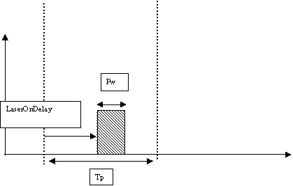
Pw = (Tp - LON - LOFF) * GrayScaleValue
GrayScaleValue |
defined from 0 to 1 ( normally in 1/256 Steps) |
|---|---|
LON |
LaserOnDelay |
LOFF |
LaserOffDelay |
LON has the special effect that it offsets the start of the pulse within Tp.
Amplitude Modulation (AM)
For AM the GrayScaleValue will be transformed linearly to the analog output value.
Analogoutput = GrayScaleValue * MaxOutput
MaxOutput corresponds to maximal achievable Output voltage of the Digital to Analog Converter Output.
|
If one of the following conditions is valid no output takes place: |
|---|
·Tp < 10 OR Tp > 655350
·(Tp - LON - LOFF) < = 0
·dx == 0 AND dy == 0
