<< Click to Display Table of Contents > 

SAMLight Manual > Option Optic3D > Features > 3D Surfaces > Cone

Cone
Previous pageReturn to chapter overviewNext page

video-icon

Check out our SAMLight Video Tutorial regarding the Optic 3D Cone:

https://youtu.be/FoQ-001nqkQ

This sub chapter describes the available settings for the mapping of an object onto a conical surface.


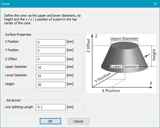
The surface configuration can be accessed by selecting Cone from the 3D Surface drop-down menu and clicking the Settings button.
 

cone_settings

Figure 521: 3D Surfaces Cone Configuration Dialog

Surface Properties: Defines the geometry and position of the vertical cone.

X Position: Defines the X position of the center of the upper surface.

Y Position: Defines the Y position of the center of the upper surface.

Z Offset: Defines the Z position of the upper surface

Upper Diameter: Defines the diameter of the upper surface.

Lower Diameter: Defines the diameter of the lower surface.

Height: Defines the height of the cone.

Advanced: Contains additional settings for projection onto a conical surface.

Line Splitting Length: Defines the distance along a line after which an additional point is generated and transformed onto the 3D surface. Each line is processed independently.

Please see below an example of a mapped text entity in the View2D (left) and 3D View (right). Please note that the 3D View can be activated by clicking on the icon 3D_View in the toolbar.

In the View2D, the innermost circle represents the Upper Diameter, and the middle circle represents the Lower Diameter. The outermost circle represents the envelope surface, which defines the full area available for marking.
By default, text entities are not curved along the surface envelope. To optimize the mapping of text onto the curvature, enable Radial Text in the Text2D Properties.

cone_2D
Figure 522: 3D Cone in View2D

cone_3D

Figure 523: 3D View of the Cone

note

For optimal marking quality, keep the marking area centered beneath the laser. Moving it too far away from the center reduces the laser incidence angle and may result in lower marking quality.
 
If the conical surface contains steep or highly inclined areas, better marking results can often be achieved by projecting the vectors from above, exporting the 3D vectors via CCI, and subsequently rotating the vectors to the desired angle. For additional information, refer to Marking on the side of a 3D surface.

note

Please note that points and point clouds are not visible in the 3D preview.