|
<< Click to Display Table of Contents > Marking on the Side of a 3D Surface |
  
|
|
<< Click to Display Table of Contents > Marking on the Side of a 3D Surface |
|
Due to the nature of projections onto STL models, and to a lesser extent when using true-length wrapping on predefined surfaces, objects projected onto the side of a 3D surface may become distorted. This occurs because the angle between the projection direction and the target surface becomes increasingly steep.
Some distortions can be reduced in advance. For example, when placing text on curved surfaces, enabling Radial Text can help maintain a more consistent appearance.
Another approach is to project the geometry from above, export the 3D vectors using CCI, and then rotate the vectors to the desired angle.
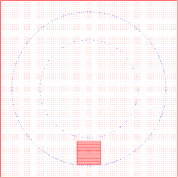
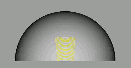
A simple example is projecting a square onto the side of a sphere. As the square is positioned farther away from the top of the sphere, its angles and edge lengths become increasingly distorted because the angle between the projection direction and the surface becomes more acute.
|
|
Figure 527: Square at the Side of a Sphere
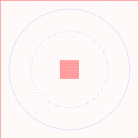
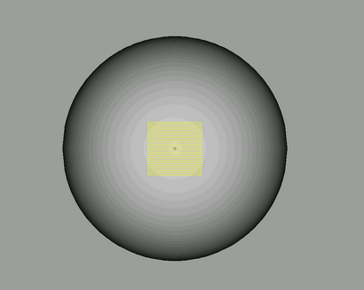
To optimize the marking result, the square can be placed at the top of the sphere, where the projection occurs at a much more favorable angle. This minimizes distortion and helps preserve the original shape and proportions of the geometry.
|
|
Figure 528: Square at the Top of a Sphere
Using the CCI command to export the transformed vectors, the projected 3D vectors can be saved as a separate job while retaining all 3D information generated during the projection process. This new job can then be opened in SAMLight, where the vectors can be rotated and transformed to the desired position, as if they had originally been placed on the side of the surface. At this stage, the 3D surfaces must be disabled.
The example below shows a square that was exported using this method and then positioned on the side of a sphere. Note the differences between this image and the first.
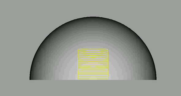
Figure 529: Square at the Side of a Sphere with CCI Commands
The resulting square exhibits significantly less distortion when it is projected from above and then moved to the desired position afterward. Please note that the sphere shown in the background is included only for visualization purposes, to display the square at the same location as in the original example. In the new job, the 3D surfaces are no longer required.