|
<< Click to Display Table of Contents > USC Connectivity |
  
|
|
<< Click to Display Table of Contents > USC Connectivity |
|
Follow each step of the flowchart to solve your connection error. If you run into any problem, please inform us where you got stuck. Further information is available at the linked topics.
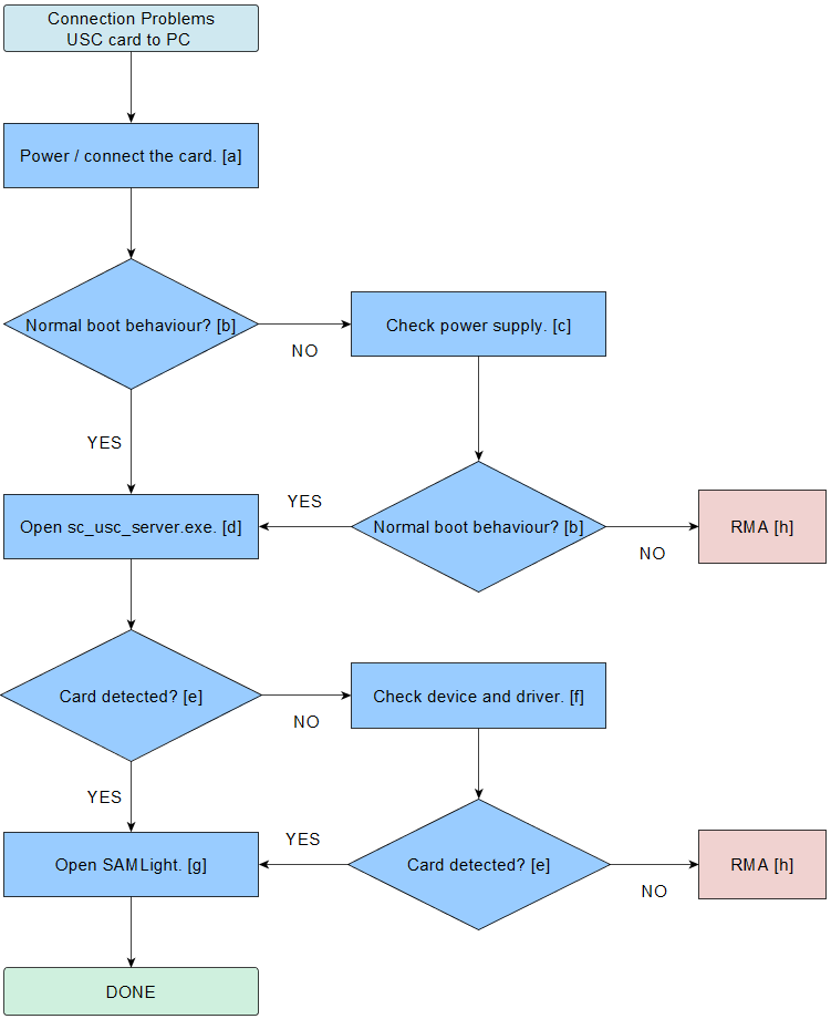
Figure 39: Connection test USC card to PC.
[a] Power / connect the card: •USC-1: Power the card externally via the 37-pin connector and remove jumper 4 (JP4) next to the USB-port and connect the card via the USB-port. It is also possible to power the USC-1 card via the USB connector (using JP4). The external power supply is highly recommended. For further information, have a look at the USC-1 manual. •USC-2: Power the card externally via the 37-pin connector and remove jumper 4 (JP1) next to the USB-port and connect the card via the USB or Ethernet port. Make sure that the card is provided with an external voltage of 5V (measured at the 37-pin connector). It is also possible to power the USC-2 card via the USB connector (using JP1). The external power supply is highly recommended. For further information have a look at the USC-2 manual. •USC-3: The USC-3 card has to be powered externally through the 37-pin connector. Make sure that the card is provided with an external voltage of 5V measured at the 37-pin connector. Connect the card to your PC via the USB or Ethernet port. For further information have a look at the USC-3 manual. [b] Normal boot behaviour? •USC-1: After powering, the green LED starts to flash a few times and then stays constantly on. Now the card is ready. If the green LED is flashing very fast something went wrong during the boot process. Please reboot the card. •USC-2/-3: After the powering, the blue LED goes on and stays on. The green LED starts to flash and then stays constantly on. Now, the card is ready. If the green LED is flashing very fast something went wrong during the boot process. Please reboot the card. (The boot process may take a bit longer for the USC-3 than for the USC-2.) [c] Check power supply: •General: If no LED turns on or flashes, please check the connection to the PC or the external power supply. The card should get an input voltage of 5V measured at the 37-pin connector. Please test different USB cables and different USB ports at the front and at the back side of the PC (see USB Connection). If possible test the same at another PC. The USC-3 has always to be powered externally. •USC-1: Try to power the card externally via the 37-pin connector. Remove jumper 4 (JP4) next to the USB-port. Make sure that the card is provided with an external voltage of 5V. •USC-2: Try to power the card externally via the 37-pin connector. Remove jumper 1 (JP1) next to the USB-port. Make sure that the card is provided with an external voltage of 5V. •USC-3: The USC-3 card really does need 5.0V measured at the 37-pin connector at the card. To guarantee enough voltage for the boot process, it is possible to supply with more than 5V, e.g. 5.5V or even up to 6V is possible for the USC-3 card. [d] Open sc_usc_server.exe: The sc_usc_server.exe shows all connected cards. It can be found in <SCAPS>\system. Normally this application runs in the background. Now, start this application in visible mode. [e] Card detected?: After a USC card has been connected and powered, it should appear in the sc_usc_server.exe. [f] Check device and driver: •Check the USB connection: Test different USB cables and different USB ports at the front and at the back side of the PC. If possible test the same at another PC. •Open the windows device manager. A USC card needs two different drivers, the Jungo WinDriver and the Scaps USC Driver. •Check for Jungo Connectivity → WinDriver1230. In the case that you have an older version installed the name could differ WinDriverXXXX. Do a right click and update the driver. The version should match the shown version in the sc_usc_server.exe. •Check for SCAPS USC : USB Scanner Controller containing a subfolder SCAPS USC-#: USB Scanner Controller. Whereby # stands for the type (1, 2 or 3) of the USC card. oIf the card is shown here and there is still no connection go to View → Show hidden devices. Maybe some other / earlier installed cards are now shown. Please uninstall each of them. Then open the sc_setup.exe to Uninstall USC Driver and Install USC Driver. Then reconnect the card, it should be displayed now in the windows device manager. oIf the card is not shown here please have check the USB-Controller. A USB-Dongle is listed as CBUSB Ver 2.0. If a USC card has not been detected in the previous steps please check if Unknown USB device is displayed. Make sure that the USC card is this device by removing the connection and reconnection, while checking if the Unknown USB device disappeares and appears again. Then open the sc_setup.exe to Uninstall USC Driver and Install USC Driver. •USC-2/-3: Both cards can be connected via Ethernet. To test the connection please connect, power the card and remove jumper 2 (JP2) next to the Ethernet port. Then open a console on your PC and type in ping 192.168.1.2 for the USC-2 and ping 192.168.1.3 for the USC-3 and enter. Then check if the card is detected. For further information can be found at the LAN connection. [g] Open SAMLight: If the card is detected you can open the software SAMLight. [h] RMA: If the previous steps could not solve your problem, parts of the hardware could be defective. In this case, please send us an e-mail to info@scaps.com with the following information: •Card-type •Serial number •Dongle-ID •Short error description |
|---|