|
<< Click to Display Table of Contents > Scanner Output - XY2-100 |
  
|
|
<< Click to Display Table of Contents > Scanner Output - XY2-100 |
|
If there are any problems with the scanner output, e.g. one axis does not move or a wobbling axis, please have a look at certain signals on the used scan head connector as shown in the table and picture below. All levels are TTL compatible, the period for CLK signals is 2 MHz, for SYNC signals 100 kHz. A second test to verify that proper data is sent via the XY2-100 interface is to test the level of the used data pins. The pin connection is shown in the respective manual.
All CLK and SYNC signals have to be as displayed below, otherwise please contact SCAPS for further steps.
|
The scan head has to be disconnected from the scanner controller for the measurement, because the goal of this test is to verify if the card sends the signals correctly. Please ensure the GND connection to avoid noisy signals. |
|---|
|
The high level should be at least 4.5 V in respect to the USC GND. |
|---|
Controller |
CLK+ |
CLK- |
SYNC+ |
SYNC- |
|---|---|---|---|---|
USC-1 (25 pin) |
Pin 14 |
Pin 1 |
Pin 15 |
Pin 2 |
USC-2/-3 (25 pin) |
Pin 14 |
Pin 1 |
Pin 15 |
Pin 2 |
USC-2/-3 HEAD2 (26 pin) |
Pin 2 |
Pin 1 |
Pin 4 |
Pin 3 |
Table 53: Scan head signals for test measurement
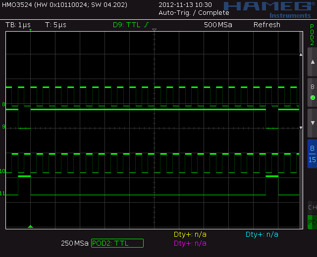
Figure 38: XY2-100 CLK + SYNC
|
Signal 8 = CLK+ |
|---|
bit |
binary |
|---|---|
-32768 |
1000000000000000 |
-32767 |
1000000000000001 |
-2 |
1111111111111110 |
-1 |
1111111111111111 |
0 |
0000000000000000 |
1 |
0000000000000001 |
32766 |
0111111111111110 |
32767 |
0111111111111111 |
Table 54: XY2-100 position data encoding

