|
<< Click to Display Table of Contents > MultiHead |
  
|
|
<< Click to Display Table of Contents > MultiHead |
|
If more than one head is set up, there are some additional functions, such as the algorithm for splitting vectors and the head assignment for each vector.
When the software starts, the View2D shows the working areas for all installed heads and the overlapping region.
Checking the AutoSplitMode recalculates and splits the vectors after each change of the job. For not too complex jobs this option is very helpful. The head color mode shows the drawings in head specific colors. Once the Head Color Mode checkbox is activated, the colors in the dialog do not tell which pen is used but instead the colors mean which head is used for marking the entity.
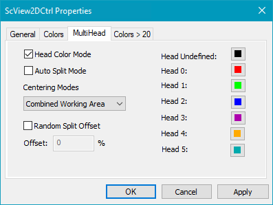
Figure 195: ScView2DCtrl_multihead
Head Color Mode: If enabled one can define a color for each head. All entities within one head will be shown with the defined color here. If disabled, the colors defined in the pens are used.
Auto Split Mode: Each entity will be automatically assigned a head if it is in its working area. If not checked a manual MultiHead Split is required.
Centering Modes: Define the reference of the possible centering modes: ![]()
Combined Working Area: Use the combined working area for centering.
Automatic: If a part of an entity is located in a head, it will be centered on this head.
Ask User: A window is opened where the user can choose on which head the centering should be executed. Choose the wanted head in the drop down menu.
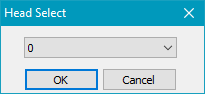
Figure 196: MultiHead centering reference head
Random Split Offset: Function is similar to Cog Vectors in Overlap Area. If enabled a percent value can be defined. The overlapped area of 2 heads will then be splitted randomly.
Default MultiHead colors:
Head number |
Color |
RGB HEX |
RGB DEC |
|---|---|---|---|
Head undefined |
|
000000 |
000 000 000 |
Head 0 |
|
ff0000 |
255 000 000 |
Head 1 |
|
00ff00 |
000 255 000 |
Head 2 |
|
0000ff |
000 000 255 |
Head 3 |
|
aa00aa |
170 000 170 |
Head 4 |
|
ffaa00 |
255 170 000 |
Head 5 |
|
00aaaa |
000 170 170 |
Table 24: Default MultiHead colors
|
In case of an error message "Galvos out of range" when the marking should start, the Splitting has not been activated. To solve the problem, right click in the View2D and either do a MultiHeadsplit or activate the AutoSplitMode in ViewProperties → MultiHead. It might also be a problem of the dimension check. Please select "No Check" in the OpticModuleProperties. |
|---|
|
It is possible to manually assign which scanner head is used to mark this entity under Entities Properties -> Entity Info page. MultiHeadSplit and Auto Split Mode take only into effect, when in Entity Info Page: Head ID is 'Auto'. |
|---|
