|
<< Click to Display Table of Contents > OpticModuleProperties |
  
|
|
<< Click to Display Table of Contents > OpticModuleProperties |
|
If MultiHead license is active: By clicking with the right mouse button in the preview window the following dialogs are being opened:
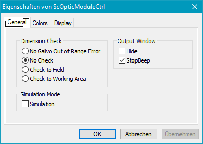
Figure 325: General of ScOpticModuleCtrl
Dimension Check: With these options, the user can select or disable different position checks.
No Galvo Out of Range Error: If No Galvo Out of Range Error is chosen, the marking will be executed without any check. If the position gets out of the boundary during marking, an overflow happens.This option is useful for MOTF jobs which are bigger than the field and should be executed without MOTF splitting. See example "Splittless MOTF of oversized jobs".
No Check: If No Check is chosen, the marking will be executed without check. If the position gets out of the boundary during marking, a galvo out of range error occurs.
Check to Field: Check whether all the entities are inside the optical field before marking is started. If this is not the case, an object outline out of range error occurs.
Check to Working Area: Check whether all the entities are inside the working area before marking is started. If this is not the case, an object outline out of range error occurs.
Simulation Mode: This function is only designed for a user who has his own simulation application. Simulation Mode means there is no hardware output. The whole marking process will be simulated by software only, for example the time of Mark could be evaluated.
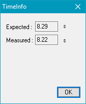
Figure 326: Time Info
|
The Simulation Mode will be automatically switched off by clicking on Mark in mark-dialogue of SAMLight. |
|---|
Output Window: This is also only designed for a user who has his own Start-Mark-Application. The output window refers to the Mark trigger window. In SAMLight, it is default that the mark trigger window is being hidden. But in the user's own application, he could set it up here and decide if he wants a beep when he clicks stop.
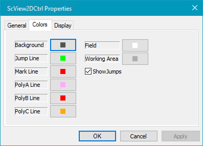
Figure 327: Colors
In the Window/1 Preview, click Mark → Preview, then the entities in Window/2 Main are plotted in different colors, which are defined in this dialog.
Default preview colors:
Line type |
Color |
RGB HEX |
RGB DEC |
|---|---|---|---|
Background |
|
555555 |
085 085 085 |
Jump line |
|
00ff00 |
000 255 000 |
Mark line |
|
ff0000 |
255 000 000 |
PolyA line |
|
ffaaff |
255 170 255 |
PolyB line |
|
ff0000 |
255 000 000 |
PolyC line |
|
ffaa00 |
000 170 170 |
Field |
|
ffffff |
255 255 255 |
WorkingArea |
|
aaaaaa |
170 170 170 |
Table 43: Default preview colors
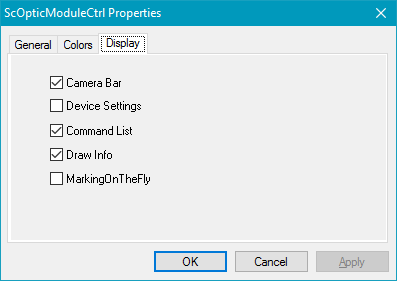
Figure 328: Display
With these check boxes, the user can activate or deactivate some toolbars or windows in the Preview Window.
