|
<< Click to Display Table of Contents > Handling Up and Downskin |
  
|
|
<< Click to Display Table of Contents > Handling Up and Downskin |
|
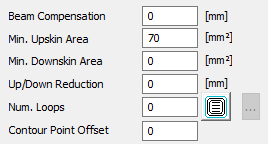
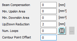
Sometimes, it is necessary to prepare the data regarding Up and Downskin. An example is given below:
|
|
|---|
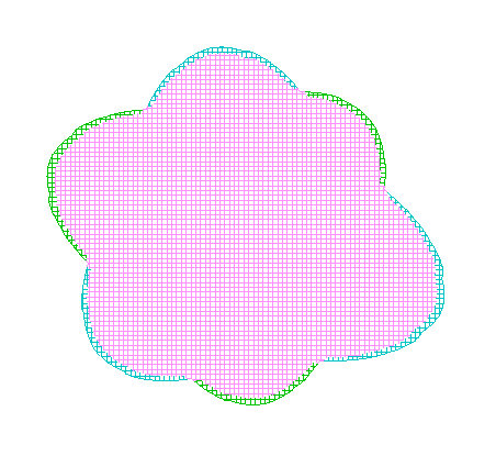
Figure 463: Up and Downskin on a hatched object
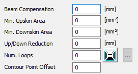
In the picture above, a 3D contour is hatched. At the borders of the object, Upskin ( blue lines ) and Downskin ( green lines ) areas are visible. To discard these areas, you can define a Min. Upskin or Min. Downskin area. See the following pictures:
|
|
|---|
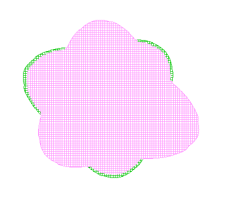
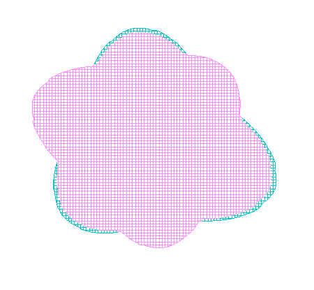
Figure 464: Upskin erased with Min. Upskin Area
In the picture above, it is shown how the blue lines = Upskin are erased by setting Min. Upskin Area = 70 mm².
|
|
|---|
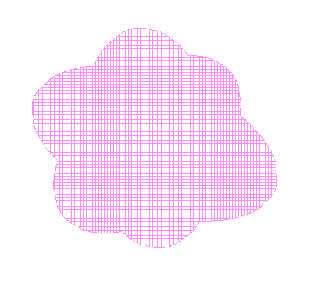
Figure 465: Downskin erased with Min. Downskin Area
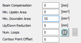
In the picture above, it is shown how the green lines = Downskin are erased by setting Min. Downskin Area = 55 mm².
|
|
|---|
Figure 466: Up and Downskin erased with Up/Down reduction
In the picture above, it is shown how the green lines = Downskin and the blue lines = Upskin are erased by setting Up/Down reduction = 2 mm.
|
For better visualization, the example was sliced with thicker slices. The settings are quite "coarse", accordingly . |
The marking order of Upskin, Downskin, Core and the contour can be set:
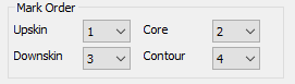
Figure 467: Mark Order
When "Split" is selected for the Contour, the border will be split into Upskin, Downskin and Core. When a specific order is selected, all contours are put in the border entity and are assigned the style for core.
At the same time, this activates the feature for individual distances and pens for each contour loop (manual borders).