|
<< Click to Display Table of Contents > Using Num Loops |
  
|
|
<< Click to Display Table of Contents > Using Num Loops |
|
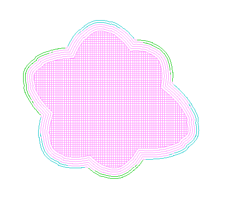
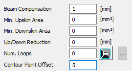
If necessary, the contour lines can be repeated, aligned to the border line of the hatched object. This can be done by defining a distance of these lines with Beam Compensation and the amount of lines using Num. Loops. Below is an example for Beam Compensation = 1 mm and Num. Loops = 5.
|
|
|---|
Figure 470: Using Num. Loops for a hatched object
There is a button next to Num. Loops with which the user can select the order of the contour marking from the inside to the outside or from the outside to the inside.
Contour Point Offset shifts the starting point for marking the contour lines by the given number of points.
|
Negative Num. Loops are possible when choosing a negative Beam Compensation. Marking from the outside in is beginning from the contour is this case, and marking from inside to outside is choosing the marking order towards the contour. |
|
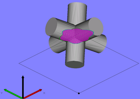
For better visualization, the example was sliced with thicker slices. The settings are quite "coarse", accordingly . |
When a specific order for Upskin, Downskin and Core is selected, the feature for individual distances and pens for each contour loop is activated.
When clicking "...", a new dialog is opened:
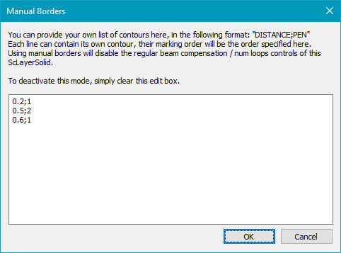
Figure 471: Manual Borders
For each loop you want to mark, please enter the desired distance / beam compensation and the pen, separated by semicolon.
Each new line will add an additional loop. The first loop will always be the original contour.
|
The pairs can also be separated by | instead of beginning a new line, e.g. 0.2;1|0.5;2|0.6;1 .
|
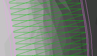
Figure 472: Visualization of manual borders example (original contour not shown)