|
<< Click to Display Table of Contents > Styles for Layers |
  
|
|
<< Click to Display Table of Contents > Styles for Layers |
|
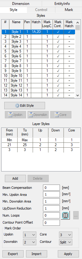
To use this feature, the checkbox "Use Styles for Layers" has to be activated in Settings → System → 3D. Then, the Styles property page will be visible. This feature lets you define Pen, Hatch, Mark Loop Count, Mark Contour and Mark Hatch for each Styles, as well as enabling you to use the Upskin and Downskin features. This means that each layer is divided into sub-areas depending on the content of the layer above and below this specific layer. Upskin is called the area of the current layer which is without content in the layer above, Downskin is called the area of the layer which has no content in the layer below.
Figure 458: Styles Properties |
Edit Style: Opens the Edit Styles dialog in which you can define a Pen, Hatch, and Mark Flags for each Style. Upskin, Downskin, Core: If a ScLayerSolid entity is available, which is the case if you have sliced a ScTriaMesh3D object, you can define each style to Up- or Downskin or to Core for each Layer. Upskin is the area of the current slice that is not topped by the following slice, Downskin is the area of the slice which has no slice beneath it. From - To: Defines a range of ActDist for the selected Style. In this case Style 1 is applied for the starting layer to the end layer interrupted by Style 2 for layers between 21 to 25 mm and also interrupted by different settings for layer at 3 mm.
Add: Add new From - To definition for Styles. Delete: Deletes a From - To definition. Beam Compensation: Reduces marking area for all layers. Min. Upskin/Downskin Area: Upskin/Downskin areas smaller than this value will not be created. Up/Down reduction: Will enlarge the adjacent layers by that value before determining Upskin/Downskin areas. This will reduce the respective areas in order to compensate for irregularities. Num. Loops: The contour lines can be repeated, the distance is defined by the Beam Compensation. With the button next to Num. Loops, the user can select the order of the contour marking from the inside to the outside or from the outside to the inside. The contour is always marked first.
Contour Point Offset: Shifts the starting point for marking the contour lines by the given number of points. Mark Order: The marking order of Upskin, Downskin, Core and the contour can be set. Export / Import: Export or import Styles file. The type of the file is *.txt.
|
|---|
|
Within one layer (ScLayerSolid entity), the order of marking is the following: Upskin, Downskin, Core. Within each of these areas, polylines are marked first, linearrays are marked second (can be changed by "Mark Hatches First"). Within the Polylines, the order of num loops depends on the selected button (from inside to outside or vice versa). |
|---|