|
<< Click to Display Table of Contents > STL Projection |
  
|
|
<< Click to Display Table of Contents > STL Projection |
|
|
Only Black&White Bitmaps can be marked on top of a STL projection. Grayscale bitmaps are not supported. |
|---|
![]()
Figure 500: 3D Surfaces toolbar
Click on the cog wheel to open the properties dialog:
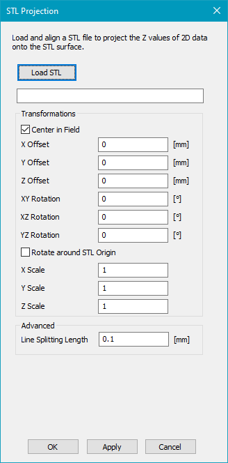
Figure 501: 3D STL property dialog
Click on "Load STL" to load a STL file. This file will be used as the surface on which the 2D vector job should be projected.
Center in Field: The STL file is centered in x and y direction in the SAMLight coordinate system. The top level of the STL file is put at z = 0 of the SAMLight coordinate system.
Offset: The STL file is translated by the given offset. This translation is done after the effect of "Center in Field".
Rotation: The coordinate system of the STL file is rotated in comparison to the SAMLight coordinate system. This rotation is done before the effect of "Center in Field". Please note that the ZY-Rotation (Rotation around the X-Axis) is in negative direction, while all other rotations in SAMLight are in positive direction. Positive rotations are counter-clockwise when the axis of rotation points towards you.
Rotate around STL origin: If this checkbox is activated, the STL is rotated around its origin. Otherwise, it is rotated around its middle.
Scale: The STL file is scaled by the given factor. This scaling is done before the effect of "Center in Field".
Line splitting length: This parameter specifies the distance along a line after which a new point is generated and transformed on the 3D surface. Every individual line is split independently.
Preview DPI: Specifies the resolution with which the STL will be displayed in the View 2D.
Enable the checkbox to the right of the cog wheel. Now the STL surface appears in the View 2D.
Below see an example where the 3D surface is a sphere and the 2D job is a simple square:
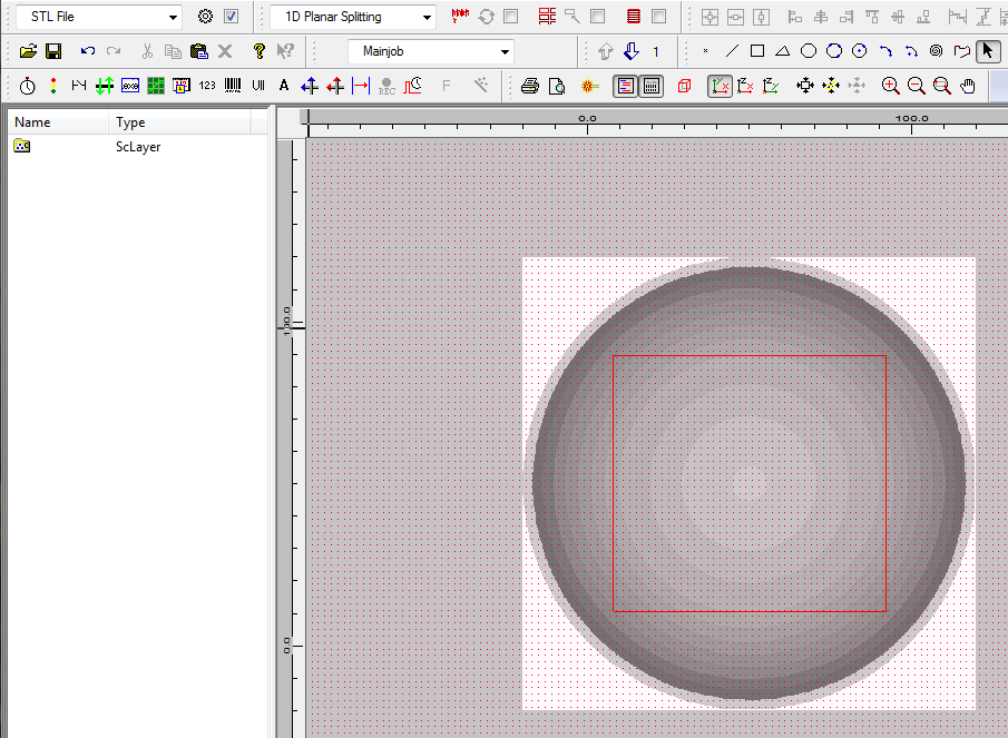
Figure 502: 2D Square projected on 3D STL sphere surface
When clicking on the Optic3D View icon ![]() you can see how the square is projected on the sphere:
you can see how the square is projected on the sphere:
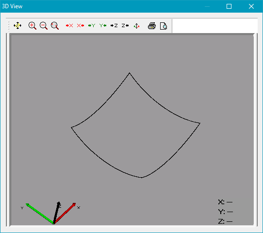
Figure 503: 3D View of the projected square.
With more extreme angles for the .STL projection, it might lead to better results to project from above, export the 3D vectors via CCI, and then rotate the vectors to the desired angle (see Marking on the side of a 3D surface).
|
For Multihead systems, it is possible to either load and modify one STL per head or load one STL for all heads.
|
|---|
.
