|
<< Click to Display Table of Contents > Cylinder |
  
|
|
<< Click to Display Table of Contents > Cylinder |
|
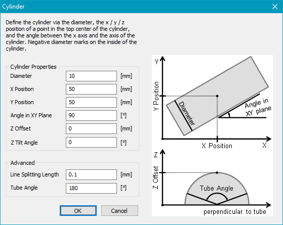
Figure 497: 3D Surfaces Cylinder dialog
Cylinder: Select Cylinder in the mode drop-down list and enable it. Click on ![]() to open the settings dialog.
to open the settings dialog.
Cylinder properties: Defines the diameter and position of the cylinder.
Diameter: Defines the diameter of the tube. Negative values are also allowed to mark inside a cylinder.
X, Y Position: Defines the X, Y position of the tube.
Angle in XY Plane: Defines the tube angle in the XY plane.
Z Offset: Defines the Z position of top of the tube. If the Diameter is negative this value defines the Z position of bottom of the tube.
Z Tilt Angle: Defines the Z slanting angle.
Advanced: Extended settings of tube marking.
Line Splitting Length: This parameter specifies the distance along a line after which a new point is generated and transformed on the 3D surface. Every individual line is split independently.
Tube Angle: Defines the maximal angle of the tube for the vector bending. This parameter affects the distance of the blue dashed lines in the View2D.
View2D: Four blue dashed lines indicates the location and size of the cylinder in the View2D. The View2D shows the vectors not bent around the tube.
Outer blue dashed lines: Defines the unwrapped size of the Tube Angle. Only vectors between these lines will be bend.
Inner blue dashed lines: Defines the wrapped size of the Tube Angle.
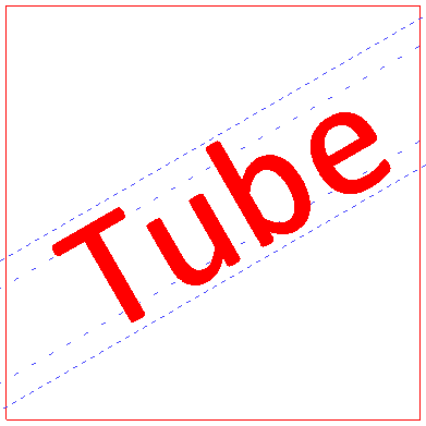
Figure 498: 3D Surfaces Cylinder View2D
3D preview: The bending of the vectors can be seen in the 3D view. Select at least one entity and click the 3D View button ![]() .
.
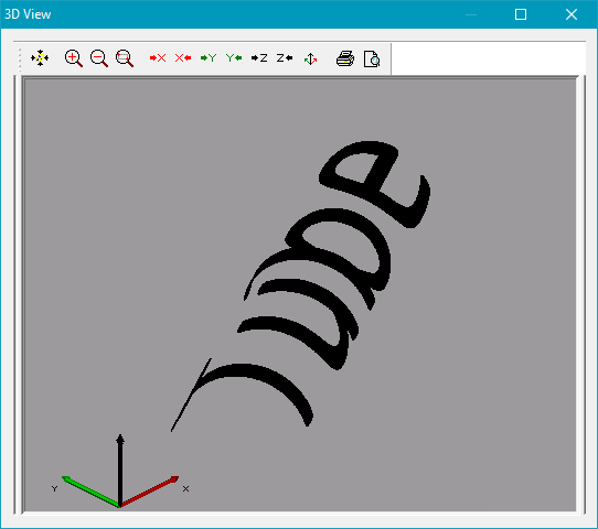
Figure 499: 3D Surfaces 3D preview.
|
To obtain optimal marking results, the entity should be centered on the surface. With further shift to the side, the angle between the laser beam and the surface gets smaller which might lead to bad marking results. |
|---|
