|
<< Click to Display Table of Contents > Gray Advanced |
  
|
|
<< Click to Display Table of Contents > Gray Advanced |
|
|
Check out our SAMLight Video Tutorial regarding the Gray Advanced Bitmap mode: |
|---|
|
USC-2 or USC-3 card required - not available for USC-1 or RTC cards. High quality bitmaps can only be achieved if an appropriate laser is used capable of fast enough power switching. |
|---|
The Gray Advanced mode is part of the improved bitmap handling and is the optimized mode for marking grayscale bitmaps. The laser power will be modulated according to the grayscale value of each pixel and in synchronization with the scanner movement along each bitmap line.
The following configuration steps in the software are necessary to mark a grayscale bitmap in Gray Advanced mode:
•Settings → System → Extras
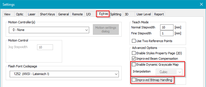
Figure 305: Presets at Settings/System/Extras
oImproved Bitmap Handling: Activate this checkbox. The improved bitmap modes offer a simplified handling of bitmaps with optimized and precise manipulation of laser signals. Only the state with activated checkbox is described in this manual.
oDynamic Grayscale Map:
▪Enable: Activate this checkbox which modifies the behavior of the System PixelMap and the Pen PixelMaps. For further information on the order of the power manipulation of the pixel maps, see Table 29.
▪Interpolation: Different modes of interpolation are available (Linear, Cubic, Hermite).
•Settings → System → Optic → Advanced (USC-2, USC-3):
oPixelAM, AM Port and PixelPWM: Select the proper option according to your laser to define which laser signal is modulated by the gray levels of the bitmap.
•Mark Property Page → Advanced
oSystem PixelMap: The global System PixelMap is a function which adjusts grayscale values. This means each grayscale value of each bitmap is mapped to an output value. The System PixelMap can be used to compensate general laser non-linearities. In addition, many laser sources should not be switched off completely for white pixels but needs a minimum laser power for fast switching between power levels.
•Pen Settings
oMain
▪Distance between dots: This displayed value is the ratio between the Speed and the Frequency. It defines the laser shot distance in the bitmap line.
▪Speed: This is the speed of the scanner while marking the bitmap lines.
▪Frequency: This is the Laser_A frequency while marking. The maximum frequency in Gray Advanced mode is 800 kHz. In Gray Advanced mode, the period (1/frequency) is rounded to 0.1 µs. Here is a list of frequencies between 20 and 800 kHz for which no rounding occurs: [20, 25, 31.25, 40, 50, 62.5, 78.125, 80, 100, 125, 156.25, 200, 250, 312.5, 400, 500, 625] kHz.
▪Jump Delay: The scanner waits this time after each jump to the next bitmap line.
▪Jump Speed: The scanner moves with this speed during jumps between the bitmap lines.
▪Note that all other delay parameters (Mark, Poly, Laser On, Laser Off) are not used in Improved Bitmap Handling mode Gray Advanced.
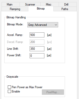
oBitmap:
|
▪Bitmap Mode: This drop down menu allows to select between grayscale and B&W bitmap modes. Select Gray Advanced. ▪Accel. Ramp: This adds a start vector for acceleration of the scanner at the beginning of each bitmap line. The length can be calculated by using the mark speed of the pen. The minimum acceleration set by the software is 2 pixel (even if Accel. Ramp = 0). ▪Line Shift: This parameter shifts each bitmap line in marking direction (especially relevant for bidirectional marking). The corresponding length to this time is calculated with the mark speed. ▪Power Shift (PixelAM only): The power modulation is shifted by this time in respect to Laser_Gate. This is useful if the laser cannot switch power levels fast enough. ▪Pen Power as Max Power: Uses the current pen power as maximum power for grayscale bitmap marking. As in all grayscale modes the power map is ignored. The factor is calculated by the current power value divided by the maximum power value. ▪Pen PixelMap: The Pen PixelMap is a function which adjusts grayscale values. This means each grayscale value of each bitmap is mapped to an output value. The Pen PixelMap can be used to optimize the bitmap output for different materials. ▪Shift Equation: Calculate Shift (Power & Line Shift): Example images with Measured Shift are shown here. |
•Select Bitmap
oImport Bitmap: Set Files of type to the desired bitmap format and import a bitmap.
oMark property page: Apply the desired pen.
oDimension property page: Scale and position the bitmap.
▪Enable the checkbox Scanner Bitmap. Without a scanner bitmap, no marking is possible.
▪Set the desired Dither Step which defines the spacing of the bitmap lines.
▪Select the radio button Grayscale.
▪Extended → Bidirectional: The order of marking the bitmap lines can be unidirectional or bidirectional. Bidirectional is the faster option to mark a bitmap due to minimized jump distances but needs more adjustments.