|
<< Click to Display Table of Contents > Optimize Line & Power Shift |
  
|
|
<< Click to Display Table of Contents > Optimize Line & Power Shift |
|
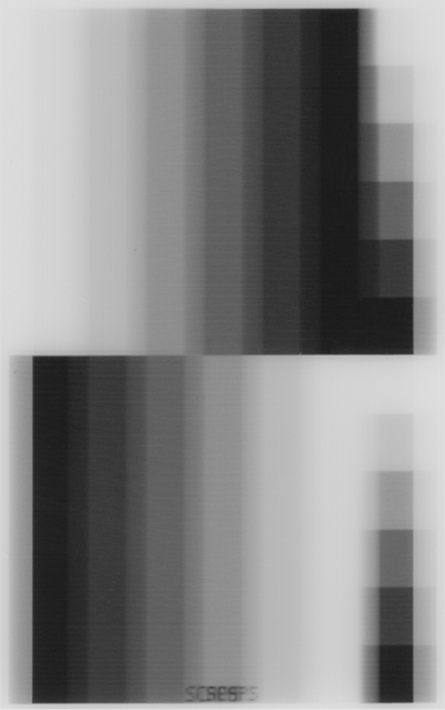
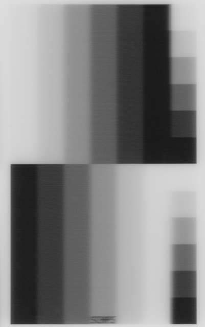
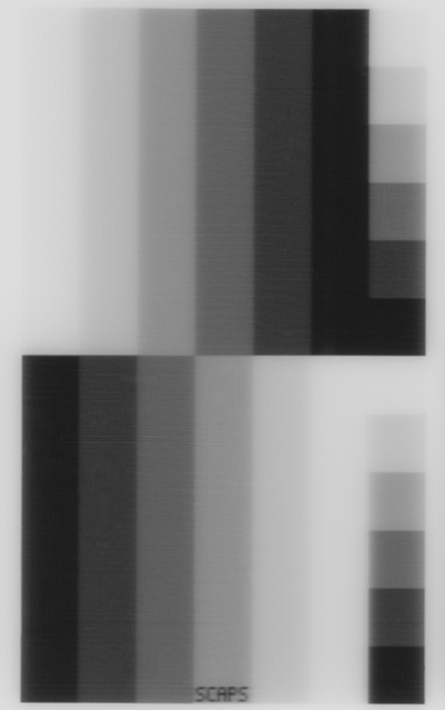
After marking the bitmap with calibrated contrast, the Line and Power Shift parameters can be adjusted. Since the shift errors are primarily visible in bi-directional bitmap marking, we now enable bi-directional. In some cases, the bitmap lines do not begin and end at the same position. Therefore, the Line Shift has to be adjusted.
Picture |
|
|
|
Bidir. Shift Effect: |
Double image at the bitmap edge and within the bitmap |
No double image at the bitmap edge, but double image (blurry) within the bitmap |
No double images at all |
Distance of the double image at the bitmap edge [mm] |
1.44 |
- |
- |
Distance of the double image within the bitmap [mm] |
1.16 |
0.28 |
- |
Line Shift [µs] [*] |
0 |
228 |
228 |
Power Shift [µs] [*] |
0 |
0 |
44 |
Table 32: Line Shift and Power Shift values
[*]: Mark Speed = 3161 mm/s and bidirectional is enabled
We did the following steps to optimize the bitmap marking:
•At the edge of the image, we measured a Line shift of 1.44 mm. With this value, we can determine the Line Shift parameter according to the Shift Equation. The example result was a Line Shift value of 228 µs. Now, the next marking can be done to check the adjustment.
•Next, we checked the structure (e.g. cross line) perpendicular to the marking direction for double images (or fringes). If such fringes are visible, the output power might currently be shifted due to the laser needing some time to set the new power value. With our laser, we determined this shift to be equal to 0.28 mm. The Shift Equation can be used to calculate the Power Shift value. In our example, it is equal to 44 µs.
•Our marking result is good and the system is now well calibrated to mark grayscale bitmaps.
For higher resolution of bitmap images, the line shift and the power shift are visible even at the the level of single bitmap lines.
•The Line Shift does not manifest as a blurry double image but as distinguishable fringes at the edges of a bitmap lines (see Figure 310).
•The Power Shift does not manifest in double images but in fringes right within a bitmap line compared to its neighbouring line (see Figure 311, A shows fringes within the chess like structure which are no longer visible in B where the correct Power Shift value is used).
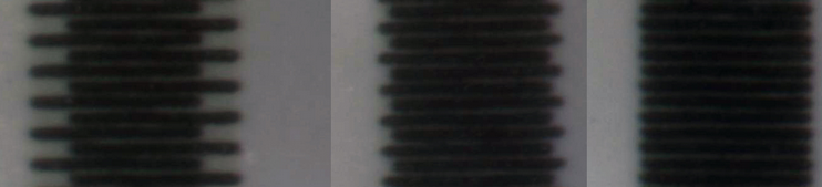
Figure 310: Bidirectional fringes at the bitmap edge change with variation of the Line Shift parameter from left (large fringes) over middle (small fringes) to right (no fringes)
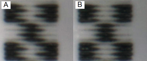
Figure 311 No fringes at the border, since Line Shift already optimized. A: Shifts for power changes within a bitmap line. B: Optimized shifts using the Power Shift parameter (compare A and B).
In the beginning, the Acceleration Ramp value has been set to 1000 µs. This parameter is important for the marking, but can be optimized to reduce the marking time.