|
<< Click to Display Table of Contents > Wobble Settings |
  
|
|
<< Click to Display Table of Contents > Wobble Settings |
|
|
Check out our SAMLight Video Tutorials: |
|---|
Marking is possible with a wobble on top of the scanner path. This wobble can be activated in the pen settings on the Scanner tab of the pen property page.
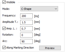
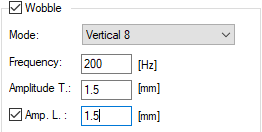
Figure 115: Wobble options |
Mode: The desired shape of the wobble is selected with the mode. Depending on the scanner control card, there are different wobble modes available, see table 16. Depending on the wobble mode, there are different wobble parameters available, see table 17. Frequency: The selected shape is repeated with this frequency. The frequency range is [1, 5000] Hz. Amplitude T.(transversal): This amplitude modifies the elongation of the shape. For some modes, this is the only parameter specifying the size. Then, the parameter is called Amplitude. For some modes, two different amplitudes can be specified. In this case, this amplitude is transversal. The range for the amplitude is [1, 10000] bit. |
|---|
Amp. L. (longitudinal): For some modes, two different amplitudes can be specified. In this case, this amplitude is the longitudinal one. It needs to be activated with the checkbox.
Rotation: Most modes can be rotated in respect to the default direction. The range for rotation is [-180, 180] deg.
Arc: This parameter defines the opening angle for C-Shape mode. The range for this arc is [1, 720] deg.
Along Marking Direction: Most wobble shapes can be aligned in respect to the marking direction. If unchecked, the alignment of the wobble shape is along the X-axis.
|
The wobble amplitude is saved in the unit bit. This means that the displayed value in mm will change if the Field Size is changed. Field gains are not taken into account. |
|---|
The following modes are available for different scanner control cards:
|
Circle |
Sine |
Ellipse |
8-Shape |
Double-8 |
Zig-Zag |
C-Shape |
|---|---|---|---|---|---|---|---|
USC-1/2, RTC3/4 |
✔ |
- |
- |
- |
- |
- |
- |
RTC5/6 |
✔* |
✔* |
✔ |
✔* |
- |
- |
- |
USC-3 |
✔ |
✔ |
✔ |
✔ |
✔ |
✔ |
✔ |
Table 16: Available wobble modes for different cards.
*: The RTC5/6 wobble modes have some restrictions. For more information see wobble setting for RTC-cards.
The following wobble parameters are available for different wobble modes:
|
Circle |
Sine |
Ellipse |
8-Shape |
Double-8 |
Zig-Zag |
C-Shape |
|---|---|---|---|---|---|---|---|
Frequency |
✔ |
✔ |
✔ |
✔ |
✔ |
✔ |
✔ |
Amplitude T. |
✔ |
✔ |
✔ |
✔ |
✔ |
✔ |
✔ |
Amp. L. |
- |
- |
✔ |
✔ |
✔ |
- |
✔ |
Rotation |
- |
✔ |
✔ |
✔ |
✔ |
✔ |
✔ |
Arc |
- |
- |
- |
- |
- |
- |
✔ |
Along Mark. Dir. |
- |
✔ |
✔ |
✔ |
✔ |
✔ |
✔ |
Table 17: Available wobble parameters for different wobble modes.
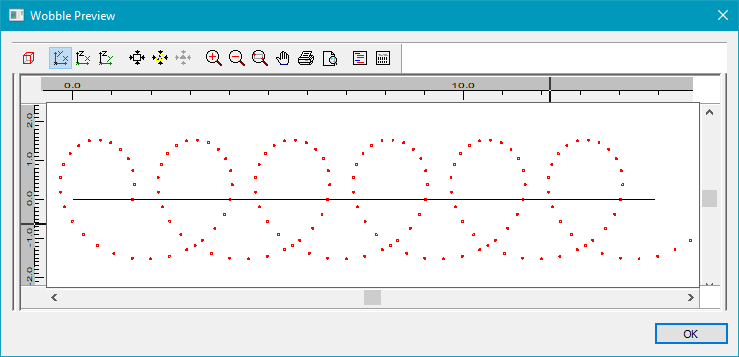
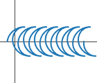
Figure 116: Wobble Preview |
The Wobble Preview uses the wobble settings in combination with the pen settings to calculate the trajectory of the wobble in comparison to a default vector in x-direction. The tool can be used to check if the current settings result in an appropriate wobble shape. The size of the wobble is shown on the left and the top. Laser Shots are shown as circles with the currently used pen color. |
|---|
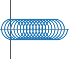
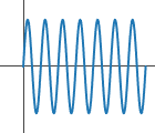
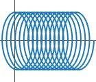
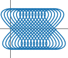
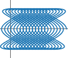
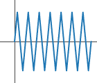
For each mode of the wobble, an example of the scanner path is given in the following.
|
Make sure that the marking entities are not too close to the edge of the field to avoid the superposition of the wobble geometry leading to out of field overflows. |
|---|