|
<< Click to Display Table of Contents > Delays |
  
|
|
<< Click to Display Table of Contents > Delays |
|
Delays: The scanner delays influence the time of the scanning process. Example: Delays for a vector with jumps from and to the home position |
|
|---|---|
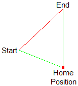
Figure 111: Single vector (red) with jumps (green) |
Figure 111 shows a simple job with: •A jump vector (green) from Home Position to Start •A mark vector (red) from Start to End •A jump vector (green) form End to Home Position Figure 112 shows the corresponding timing diagram: •The job begins with switching on the Marking in Progress (MIP) signal, while the scanner is at the Home Position. •After the Job Execution Delay (JED), the scanner jumps to Start, where it waits for Jump Delay. •Then, the scanner begins with the mark move and the laser is switched on after LaserOn delay. •Once, End is reached, the laser is switched off after LaserOff Delay, while the scanner waits for Mark Delay. •The scanner jumps to the Home Position, where it waits for Jump Delay. •Finally the MIP signal is switched off. |
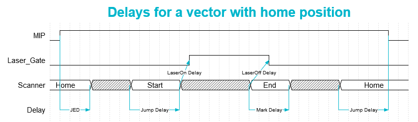
Figure 112: Timing diagram of delays for a single vector with jumps from and to the home position. MIP is Marking in progress.
Example: Delays for two subsequent vectors
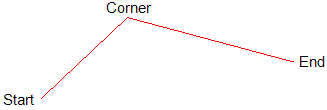
Figure 113: Two subsequent vectors meeting at the corner. |
Figure 113 shows a simple job with: •Two successive mark vectors (red) from Start to End, with a Corner in between. Figure 114 shows the corresponding timing diagram: •The job begins with switching on the Marking in Progress (MIP) signal, while the scanner begins with the mark move from Start to Corner and the laser is switched on after LaserOn Delay. •When the scanner reaches the Corner, it waits for Poly Delay. •After that, the scanner continues with the mark move from Corner to End. •Once, End is reached, the laser is switched off after LaserOff Delay, while the scanner waits for Mark Delay. •Finally the MIP signal is switched off. |
|---|
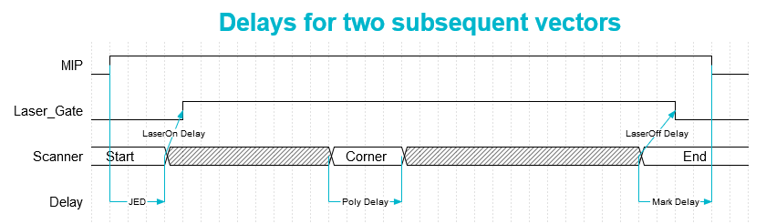
Figure 114: Timing diagram of delays for two subsequent vectors. MIP is Marking in progress.
Some delay rule conditions must be considered:
Delay rule |
Description |
|---|---|
LaserOff > LaserOn |
This is the first delay rule. In case of very short mark commands the mark command may end before LaserOn command is issued and to guarantee that the LaserOff command is not issued before LaserOn command is issued, the LaserOff delay must be greater than the LaserOn delay |
Mark + LaserOn > LaserOff |
This is the second delay rule. In case there are two marking commands in succession, the LaserOff command after mark command 1 should be issued before the LaserOn command for mark command 2 gets issued. Therefore the mark delay plus the LaserOn delay must be longer than the LaserOff delay. |
Table 14: First and second delay rule
To optimize the delays it is recommended to set the scanner delays on high values and define the laser delays first. Then the scanner delays can be optimized. |
|---|
Delay |
Effect if delay is too short |
Effect if delay is too long |
|---|---|---|
Jump |
Oscillations could occur at the start of a vector. |
No problem, just increasing mark time. |
Mark |
The last part of a vector is turned towards the direction of the jump vector. |
No problem, just increasing mark time. |
Poly |
The corners of the polyline are rounded off. |
Burn-in effects at the corners. |
LaserOn |
Burn-in effects at the beginning of a vector. |
The first part of a vector is not marked. |
LaserOff |
The last part of a vector is not marked. |
Burn-in effects at the end of a vector. |
Table 15: Marking effects of scanner and laser delays
More detailed explanations can be found at Scanner and Laser delays.