|
<< Click to Display Table of Contents > Shutter_Control |
  
|
|
<< Click to Display Table of Contents > Shutter_Control |
|
Enable Shutter Control: Enables the Shutter Control feature.
Enable Shutter for Red Pointer: Enables the Shutter Control feature for the Red Pointer.
Shutter Control Output: Defines the output used for shutter control. During operation, the applications sends open and close signals to the shutter depending on the current state. For example, the shutter is opened before the laser marking starts and closed again after marking has finished and the Shutter Enable Delay has elapsed. The signal polarity (active high or active low) can be configured with the Open Signal Level option below.
Shutter Feedback Input: Defines the input used to confirm the current shutter state (opening or closing). The input must be evaluated within the time defined in Shutter Control Timeout before and after marking; otherwise an error is triggered.
Shutter Control Timeout [s]: Defines the timeout for evaluating the Shutter Feedback Input. If the shutter state is not confirmed within the configured time before or after marking, an error message is displayed and the marking operation is canceled.
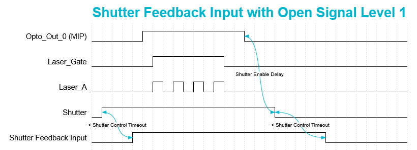
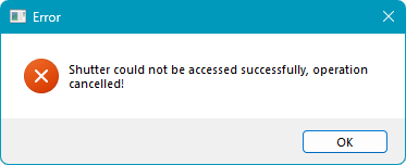
Figure 53: Shutter Control Timeout Timing Diagram Figure 54: Shutter Control Timeout Error
Shutter Enable Delay [s]: Defines a delay before the shutter is closed automatically after the last marking operation. If the laser is activated again within the configured time, the shutter remains open.
Open Signal Level: Change the signal polarity (active high or active low) of the Shutter Control Output. This option allows the scanner software behavior to match the shutter hardware signal polarity.
Level 0: Sets the Shutter Control Output to active high. If this polarity is used, configure the assigned Shutter Control Output as high in the Hardware Settings and store the configuration on the USC card. This ensures that the shutter remains closed after a reboot.
Please note that individual output inversion is only supported for USC-2 and USC-3 cards. For USC-1 and RTC cards, outputs can only be inverted globally.
If output inversion is not possible, the shutter may not operate correctly during boot and will only function correctly after the first marking operation.
Level 1: Sets the Shutter Control Output to active low. No signal inversion is required when this polarity is used.
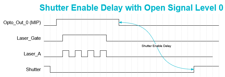
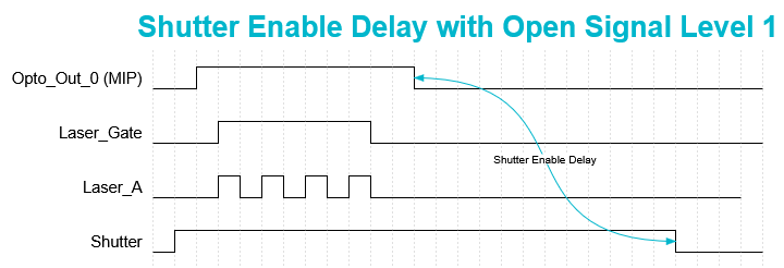
Figure 55: Shutter Control Open Signal Level 0 Figure 56: Shutter Control Open Signal Level 1