|
<< Click to Display Table of Contents > Setup |
  
|
|
<< Click to Display Table of Contents > Setup |
|
The following will guide through the steps to set up a successful marking:
There are 2 planar axes required to be connected and configured. You can find the motion settings for this here.
Afterwards you can enable the 2D Splitting Area within the SAMLight View2D. Set your coordinates as shown in the image below (these are just example values, you can place this area at any desired position according to the axes limitations):
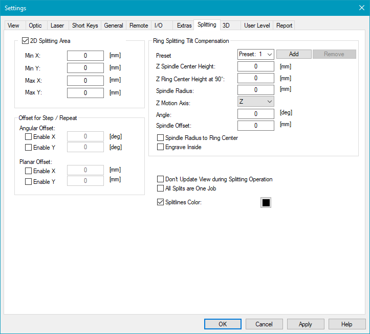
Figure 423: 2D Splitting Area Coordinates
After applying this step your View2D will look like shown below. The black dotted line indicates the 2D Splitting Area.
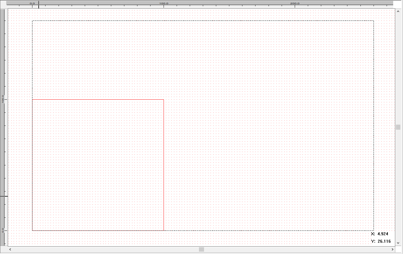
Figure 424: 2D Splitting Area Enabled
In this example the fieldsize is equal to the working area with a dimension of 100x100m and centered around (50,50) but it does not matter where the working area is located regarding the marking. Due to this you can hide the working area in the 2D Splitting Area with a right click in the View2D → ViewProperties → Show Working Area
Your working area is indicated by the red rectangle. This splitting mode does not include any GUI Updates during the marking process.
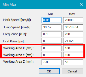
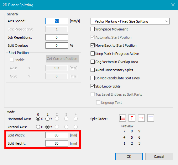
A notable restriction to this splitting mode is, that your split part can not be bigger than the set working area. In the example below you see that the working area dimensions are 100x100mm (equal to the Fieldsize in this case), the size of the split parts is set to 80x80mm.
Figure 425: Size Working Area |
Figure 426: Size Split Part |
Afterwards you can set up your job file and enable the splitting. In the following the Splitlines Color has been set to black, the default is red.
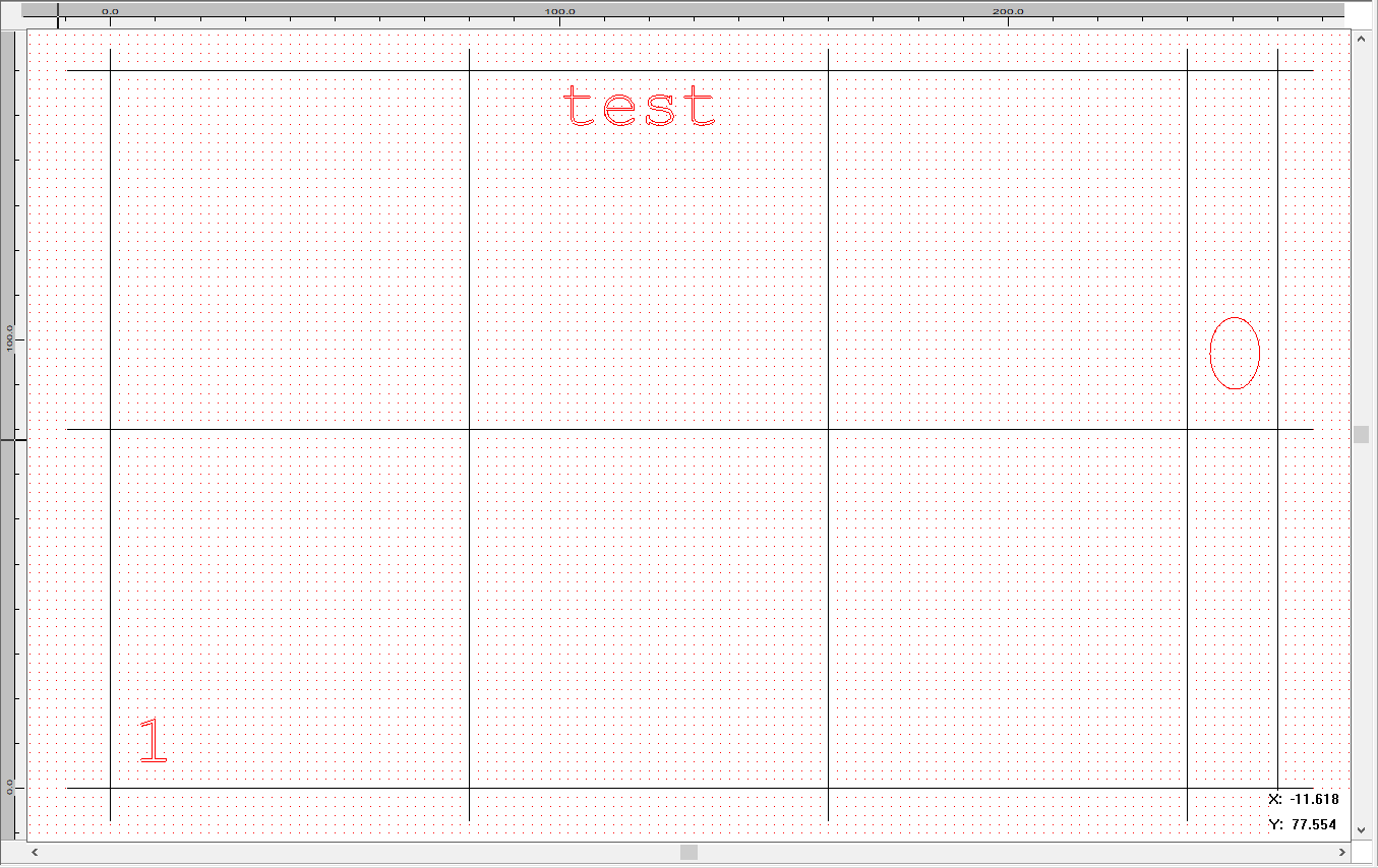
Figure 427: Job Setup and Splitting Enabled
In this splitting mode the axis coordinates are synchronized with the SAMLight coordinate.
The axes will always be moved to the central coordinate of the split part (Fixed Size Splitting).
In the following you can see that only three split parts have content to be marked.
In this example the flag Skip Empty Splits is active, so that we move directly to the center of the next split part.
The order will be defined by the Split Order within the Splitting Settings. The order of the EntityList will not influence the sequence.
In this specific example the split order is set from left to right in x dimension and from down to up in y dimension.
So in this example the axes will move to the center of the first split part, that is located at (40;40). Since empty splits will be skipped we will continue with split part 6, which center is located at (120;120). Finally the axes move to the last split part 8 with center coordinates at (250;120).
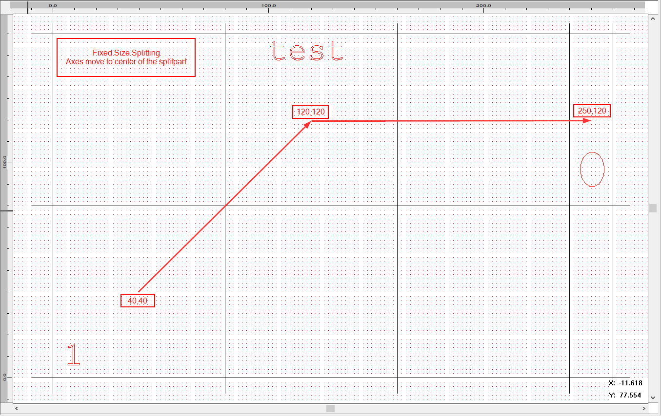
Figure 428: Axes Movement for Fixed Size Splitting (Skip Empty Splits active)
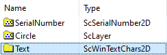
In case of Entity Based Splitting the axes will move to the central coordinate of the entity. Here you can not define the Split Order within the Splitting Settings, the order is instead defined by the order of the entities within the EntityList.
Figure 429: EntityList |
The following example contains three entities within the 2D Splitting Area. They are shown in the entity list, also specifying the marking order. Due to this the axes will move to (10,10) for the serial number entity called "SerialNumber". Then it continues to "Circle" at (250,110) and finally after marking "Text" the process is done at (120,150). Based on the flag Move Back to Start Position the axes will move back to the start position or stay there. |
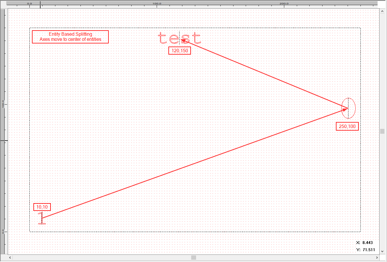
Figure 430: Axes Movement for Entity Based Splitting (Red Arrows Indicate the Movement of the Axes)