|
<< Click to Display Table of Contents > Example: Reduced Motion Area |
  
|
|
<< Click to Display Table of Contents > Example: Reduced Motion Area |
|
Example:
There is an additional option to mark a bigger field in case of limiting axis movement, leading to an increased marking area. Usually this mode is used to move the axes centered above the split part or entity itself.
In the following we use again a working area of 100x100mm. The axes can only operate in limited ranges. The limits of the axes are defined within the motion settings. Limits are currently given for x - [50;210] and y - [50;110].
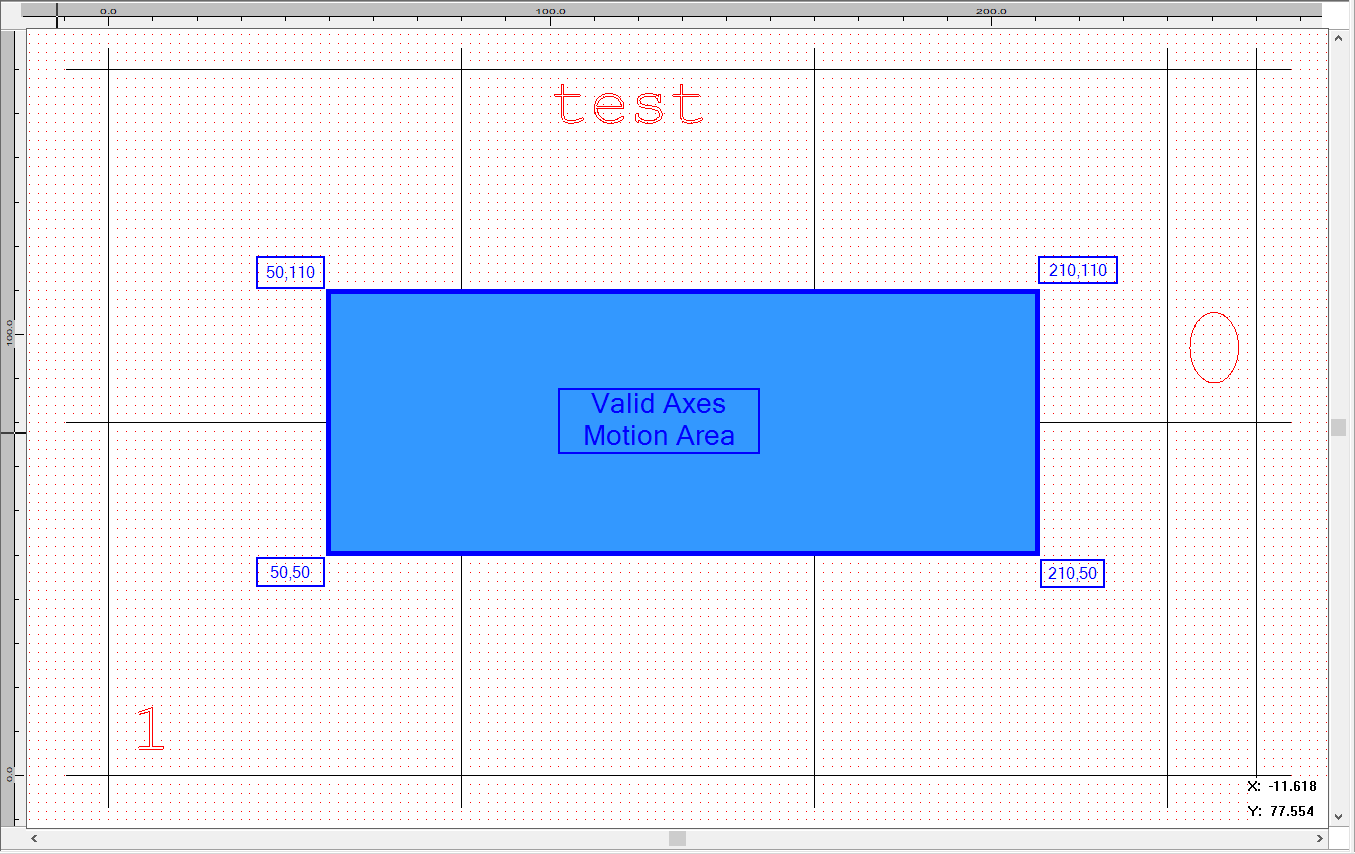
Figure 431: Axes Movement with Limits
The following image shows the axes position to execute each split part. The axes will move within their limits and the working area will be arranged in a way to completely cover the working area. The split part is therefore located within the valid marking area and can be executed.
•Case Red: Needed to execute split part 1. The axes will move to coordinates (50,50). Therefore it can cover the complete left bottom corner.
•Case Orange: Needed to execute split part 6 (empty ones also counted). The axes will move to coordinates (120,110).
•Case Green: Needed to execute split part 8. The axes will move to coordinates (210,110). Then it can cover the complete right top corner.
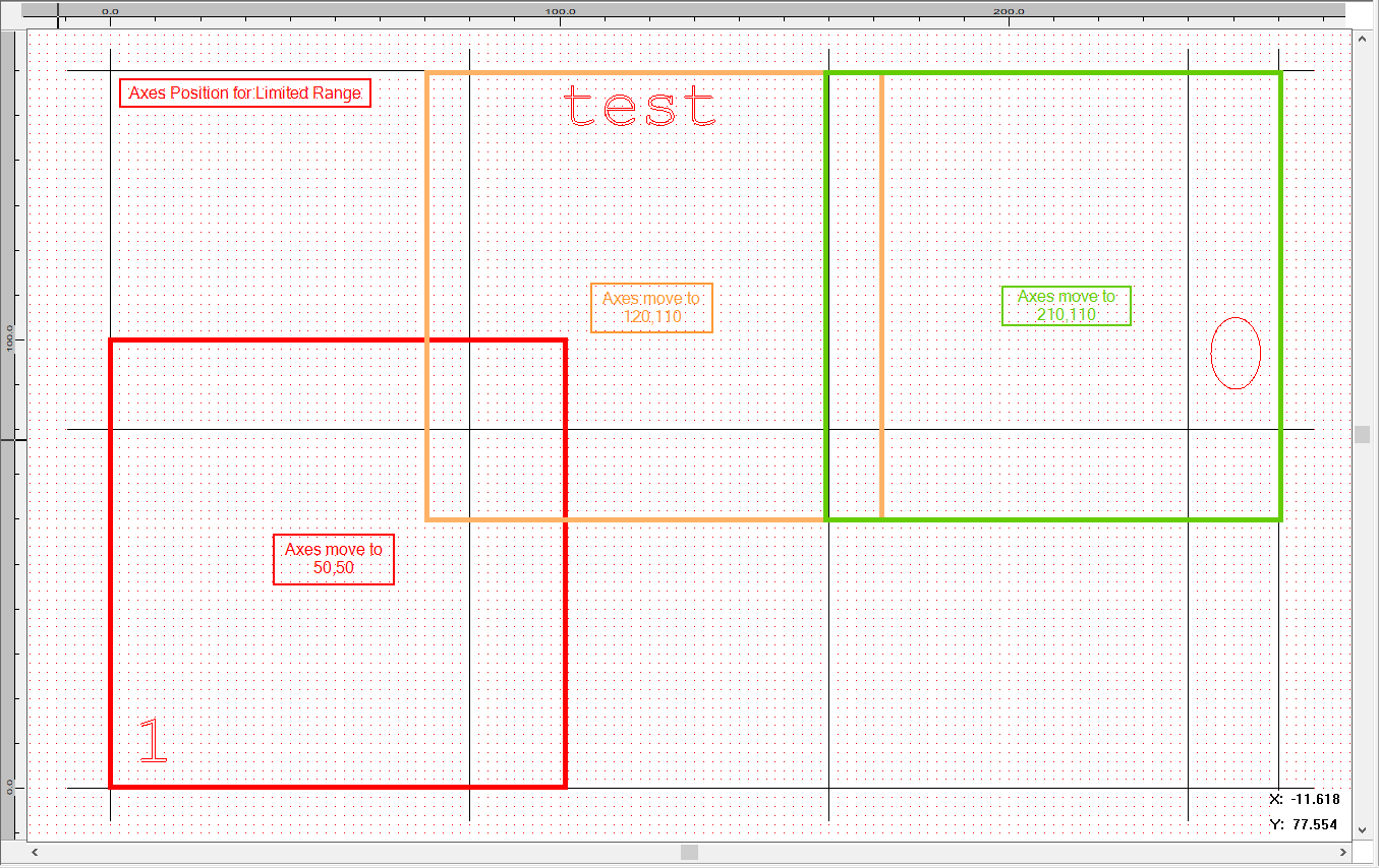
Figure 432: Positioning of the Working Area for each Filled Split Part.