|
<< Click to Display Table of Contents > Marking on Curved Parts |
  
|
|
<< Click to Display Table of Contents > Marking on Curved Parts |
|
Optic3D allows the import of 3D DXF files and provides several tools for manipulating 3D objects. Imported objects can be translated along the Z- axis, rotated around all three axes, and their 3D vectors can be edited manually.
Marking 3D line structures requires special hardware, including a compatible scanner controller card and a 3-axis scan head. In addition, a dedicated correction file must be configured. For further details, refer to Requirement & Settings.
The available marking range in the Z direction depends on the scanner's stroke (working range). A 3-axis scanner enables marking on curved or uneven surfaces by following line geometries with varying Z-values.
3D vectors can be imported via File → Import.. using a 3D DXF file (DXF Version 2). After import, the Z values of lines and points can be viewed and modified as needed.
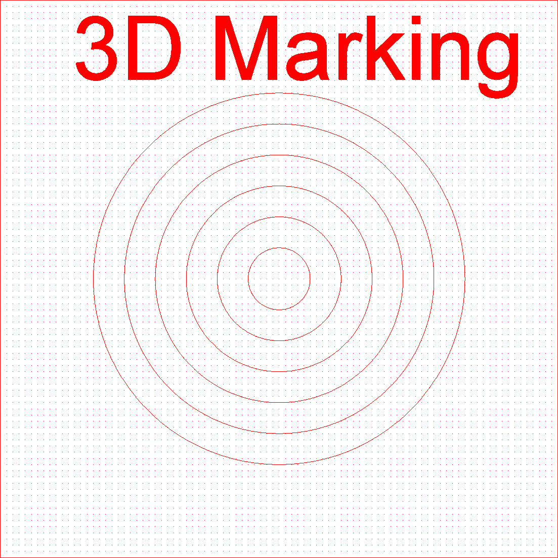
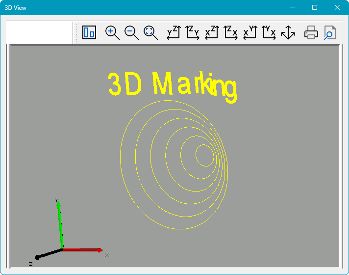
The example below shows a job containing elements with varying Z-values. The 3D View is displayed on the right, while the View2D is shown on the left. Please note that the 3D View can be activated by clicking on the icon  in the toolbar.
Figure 520: View2D with Varying Z-Values |
|
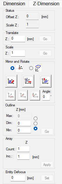
Z Dimension Property Page: The Z Dimension property page can be used to change the Z dimension of the selected entity. This page has no Apply button, the operations Translate, Scale and Outline can be executed separately by entering the values and clicking the corresponding Go button.
Figure 522: Z Dimension Property Page |
Status: Offset Z: Displays the difference in Z position between the original object and the object after transformations have been applied. Scale Z: Displays the difference in Z scaling between the original object and the transformed object. Translate: Z: Moves the entire object along the Z axis. Scale: Z: Scales the entire object along the Z axis. Mirror and Rotate: Provides functions for mirroring and rotating the selected object in 3D space. Center of Mirroring and Rotation: Defines the reference point used for mirroring and rotation operations. World Origin Object Center Mirroring: Mirrors the selected object about one of the principal coordinate planes. XY Plane: Mirrors the object across XY plane, reversing its position in the Z direction. XZ Plane: Mirrors the object across XZ plane, reversing its position in the Y direction. YZ Plane: Mirrors the object across YZ plane, reversing its position in the X direction. Rotate: Rotates the selected object about one of the coordinate axes (X, Y and Z). Enter the desired rotation angle before executing the rotation. Valid rotation angles range from -360° to +360°. The rotation buttons are enabled only when a valid angles has been entered. Outline: The Outline controls are used to position or scale the object along the Z axis. The radio buttons determine which outline parameter is edited directly. When a value is modified, the remaining outline parameters are updated automatically to maintain a consistent object size and position. To avoid conflicting operations, only one outline parameter can be edited at a time. Max: Defines the maximum Z coordinate of the object. When modified, the object's position and extent are adjusted accordingly. Dim: Defines the total extent of the object in Z direction. When modified, the object is scaled symmetrically about its center to match the specified Z dimension. Min: Defines the minimum Z coordinate of the object. When modified, the object's position and extent are adjusted accordingly. Array: The Array function creates reference copies of the selected entity along the Z axis. Reference copies in the X and Y directions can be created in the Entity Info property page. Count: Defines the number of copies to create. Inc.: Define the spacing between copies along the Z axis. Entity Defocus: Controls an additional defocus value applied to the selected entity during marking. This setting is effective only when Pen Defocus is enabled for the assigned pen. If a defocus value is assigned to a group, the same value is applied to all subentities within that group. The effective defocus used during marking is calculated as:
This allows individual entities or groups to be marked with a defocus offset relative to the defocus defined by the assigned pen. |
|
The Z-Dimension property page requires the Optic3D option. |
|---|
Point Edit Mode: The Point Edit Mode allows editing the Z coordinates of individual points of a 3D object. To enter this mode, click the Point Edit Mode button in the toolbar.
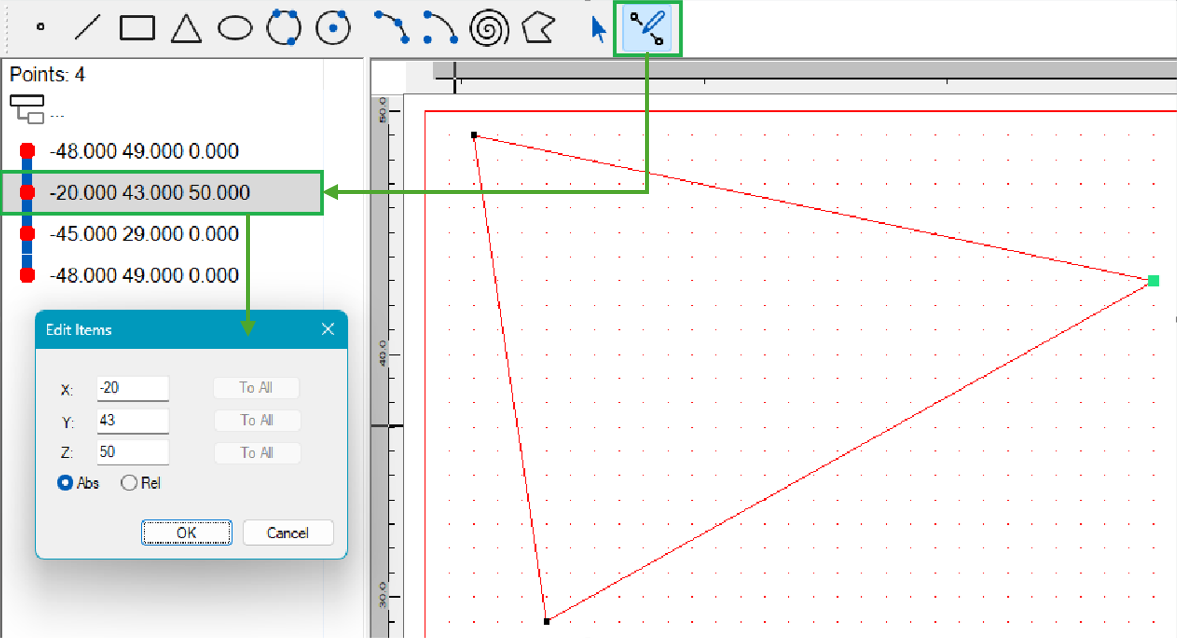
Figure 523: Optic3D Point Edit Mode