|
<< Click to Display Table of Contents > LED Indicators |
  
|
|
<< Click to Display Table of Contents > LED Indicators |
|
The three LED Indicators have the following function:
![]()
Figure 16: LED indicators
FPGA Access (FA, yellow):
•Indicates data transfer via the USB or Ethernet connection.
Mark In Progress (MIP, red):
•This LED is parallel with the opto-insulated Opto_Out_0 (pin 3) output of the 37-pin connector. It is ON during mark.
Operation (OP, green):
•OFF or blinking: The device is not operational
•ON: The device is operational
The LED's signals can be gripped at the multi-pin connector SV2. The pin assignment is shown below. If external LEDs should be connected, please use a suitable signal amplifier (e.g. buffer 74HC244).
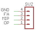
Figure 17: SV2 assignment