|
<< Click to Display Table of Contents > Optic3D USC |
  
|
|
<< Click to Display Table of Contents > Optic3D USC |
|
Requirements for SCAPS USC-1, USC-2 and USC-3 cards:
•Correction File: 2D ucf file from SCAPS.
•Required SCAPS option: FlatLense and Optic3D.
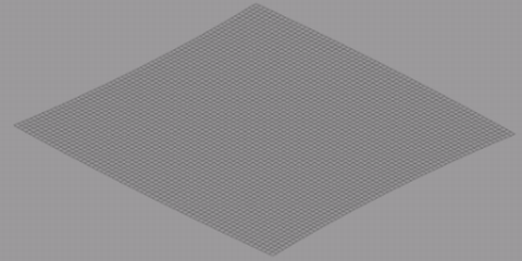
Figure 437: Shape of a 2D Correction File
Settings: For USC cards, enter the following Dialogs Settings → System → Optic:
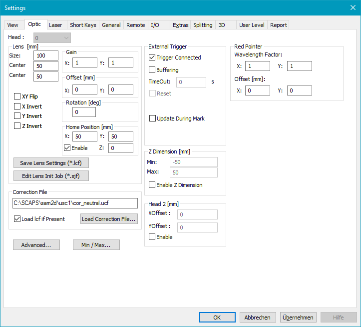
Figure 438: Settings → Optic Dialog for Z-Dimension
In this dialog the XY field size and the correction file can be defined.
Find the following Dialog for USC-1 in Settings → System → Optic → Advanced → Z-Correction (Enable) → Advanced and for USC-2 in Settings → System → Optic → Advanced → Correction, Settings → Z‑Correction, Settings.
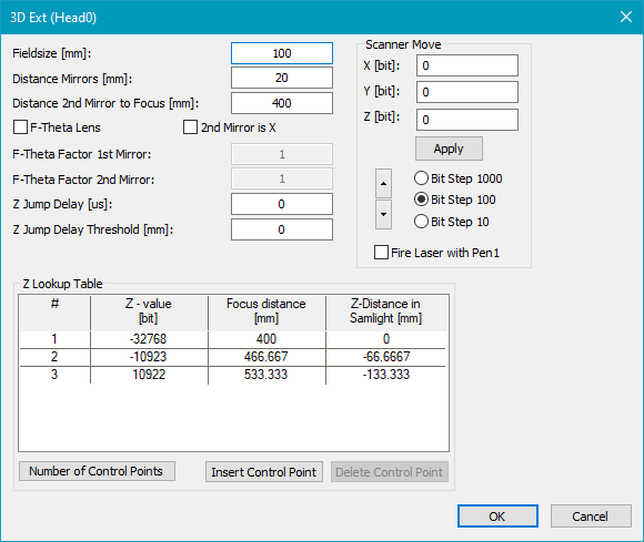
Figure 439: Z-Correction Settings
Fieldsize: The size of the XY field needs to be identical with the field size set in Settings > System > Optic.
Distance mirrors: Distance between the x and y mirror of the scan head in mm. This value is usually given by the scan head manufacturer.
Distance second mirror to focus: Distance between the second mirror to the center of the field in the focus plane.
F-Theta lens: Should be checked if in addition to the 3rd scanner axis, a F-Theta lens is mounted.
2nd mirror is X: Switches x and y values.
F-Theta factor 1st mirror/ F-Theta factor 2nd mirror: These empirical factors can be found following the description in F-theta Factor Calibration.
Z Jump Delay [µs]: Due to the fundamental difference of the Z axis it could be necessary to increase the jump delay after a big change in the Z value. The 'Z Jump Delay' is added to the normal jump delay when a jump has a Z dimension greater than 'Z Jump Delay Threshold [mm]'. A value of '0' disables this feature.
Z Jump Delay Threshold [mm]: If a jump has a Z dimension greater than this threshold the 'Z Jump Delay [µs]' is added to the normal jump delay.
Z Lookup Table: For compensating the non-linearity of the relation z axis position to focus distance, a lookup table can be defined. The lookup table contains the DAC value plus the distance from second mirror to focus when adjusting this DAC value. The points must be ordered ascending by the 'Focus Distance [mm]' value.
Number of control points: The number of control points can be between 2 and 32.
Insert control point: Insert a new control point. If no line is selected the control point will be added at the bottom, if a line is selected the point will be added above.
Delete control point: Select a control point and delete it.
XYZ Move: A helper function for finding the proper lookup table values.
High / Normal / Fine: Define Step Width for XYZ Move.
Recommended calibration procedure:
•Get the correction file from scan head manufacturer and send it to SCAPS (info@scaps.com) for being converted into a UCF file format containing no z values
•Setup hardware to right working distance (z=0 plane).
•Find the right lens size value to get a correct aspect ratio when marking for example a rectangle. 10 mm in drawing have to be 10 mm on marking (in z=0 plane). The lens value defines how many mm are related to the 65536 bits.
•Get the right mirror mounting distance values.
•Within the z calibration dialog, type in values for field size and the 2 distance mirror values.
•For getting the right calibration values for the lookup table
•Best would be having a z stage for calibration of different z heights. The valid DAC range is from -32768 to +32767. Two general ways to generate the lookup table. Either predefining DAC and varying z or the other way around.
•E.g. you create 3 control points and enter following values for DAC.
•Then you search for the focal planes d1, d2 and d3 with the XYZ Move window. For compensating further non-linearities you have to create further control points in the lookup table.
|
DAC [bits] |
[mm] |
|---|---|---|
1 |
-32768 |
d1 |
2 |
0 |
d2 |
3 |
32767 |
d3 |
Table 62: Example Z lookup table. d1 < d2 < d3