|
<< Click to Display Table of Contents > 2D Planar Splitting |
  
|
|
<< Click to Display Table of Contents > 2D Planar Splitting |
|
2D Planar Splitting is designed for splitting the current job in two directions. Therefore, no split axis definition is necessary here. When using this mode, an XY table should be used to place the workpiece at the correct position. This mode requires the connected motion controller to have at least two axes configured for planar operation.
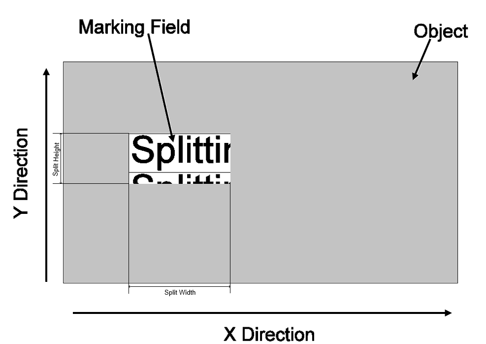
Figure 415: 2D Planar Splitting
|
If an option is grayed out in the Splitting Settings dialog, it cannot be used with the currently selected splitting option. Parameters that are checked but grayed out are not used. This mode is not optimized for splitting bitmaps. Therefore, some settings, such as Split Overlap or Cog Vectors in Overlap Area, have no effect, as they target vectors. These settings will not be grayed out for bitmaps. |
|---|
The following table lists all available parameters for 2D Planar Splitting and their availability per marking mode:
2D Planar Splitting Parameters |
Vector Marking |
|
|---|---|---|
✔ |
✔ |
|
✔ |
✔ |
|
✔ |
— |
|
✔ |
— |
|
✔ |
✔ |
|
✔ |
✔ |
|
✔ |
✔ |
|
✔ |
✔ |
|
✔ |
✔ |
|
✔ |
— |
|
✔ |
— |
|
✔ |
— |
|
✔ |
— |
|
— |
✔ |
|
— |
✔ |
|
✔ |
✔ |
|
✔ |
✔ |
|
✔ |
— |
|
✔ |
— |
|
✔ |
— |
|
Table 53: 2D Planar Splitting Parameters
Configuration of these parameters is done in the 2D Planar Splitting dialog shown below.

Figure 416: 2D Planar Splitting Dialog
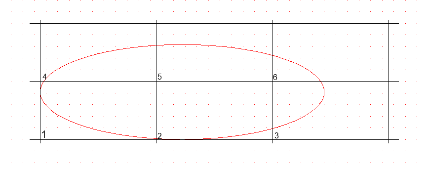
The figure below illustrates how a 2D Planar split job changes once marking is triggered via Mark → Trigger. Note that the numbers in the lower-left corner indicate the split order.
|
|
|---|
Figure 417: 2D Planar Split before and after activation of Mark → Trigger
Below are some examples of different split order:
Figure 418: Order of split parts Marking |
In this example, columns are marked one at a time, from left to right. Before each column, the scan head returns to the top, so every column starts from the same vertical position. This repeated return can reduce efficiency, depending on the speed of the motion device. |
|---|---|
Figure 419: Optimized order of split parts marking |
In this example, columns are again marked one at a time, but without a separate return movement. Instead, marking takes place while the motion device travels back toward the border, folding the return movement into the marking process itself. This reduces overall marking time. |
Figure 420: Defining the position of the split parts |
The position of the first split part is set using the two buttons in the center. The order in which the remaining split parts are marked is set using the button on the left. |