|
<< Click to Display Table of Contents > Pulse Length |
  
|
|
<< Click to Display Table of Contents > Pulse Length |
|
The following example will show how the pulse length will be electronically set:
To test if the correct pulse length is set, one can measure LP1 (Data) and LP2 (Clock) at the 8 bit digital Laser port.
To set the pulse length, a signal build out of 4 sent bytes is created.
The following example shows this for a pulse length equal to 200ns.
Byte 1 & 2 are here always the same. The pulse length information will be set within Byte 4. Byte 3 is always zero, except the value of the pulse length can not only be set via Byte 4.
•Byte 1: 0xA5 - 1010 0101
•Byte 2: 0x01 - 0000 0001
•Byte 3: 0x00 - 0000 0000
•Byte 4: 200 - 1100 1000
The following image shows the sent signals:
•Channel 0: Opto_Out_2 - Enable
•Channel 1: LP1 - Data
•Channel 2: LP2 - Clock
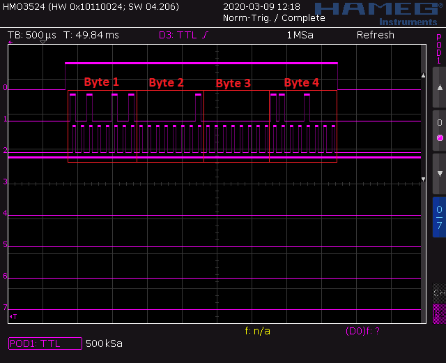
Table 15: Pulse Length 200ns