|
<< Click to Display Table of Contents > Tilted Surface |
  
|
|
<< Click to Display Table of Contents > Tilted Surface |
|
This sub chapter describes the available settings for the mapping to a tilted surface.
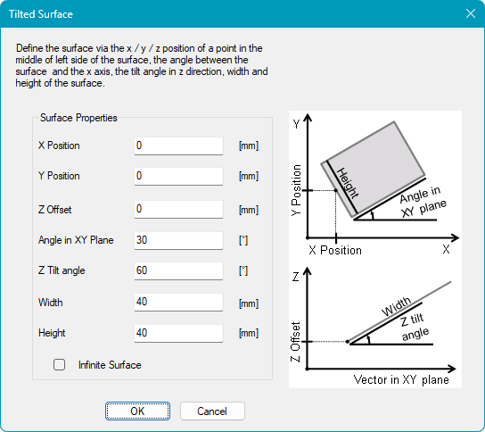
The tilted surface configuration can be accessed by selecting Tilted Surface from the 3D Surface drop-down menu and clicking the Settings button.
Figure 502: 3D Tilted Surface Configuration Dialog |
Surface Properties: Defines the geometry and position of the tilted surface. X Position: Defines the X position of the center point of one side. Y Position: Defines the Y position of the center point of one side. Z Offset: Defines the Z position of the lower edge. Angle in XY Plane: Defines the rotation in the XY plane. Z Tilt Angle: Defines the angle between the tilted surface and the XY plane. Width: Defines the width of the surface. Height: Defines the height of the surface. Infinite Surface: Creates an infinite surface when enabled. |
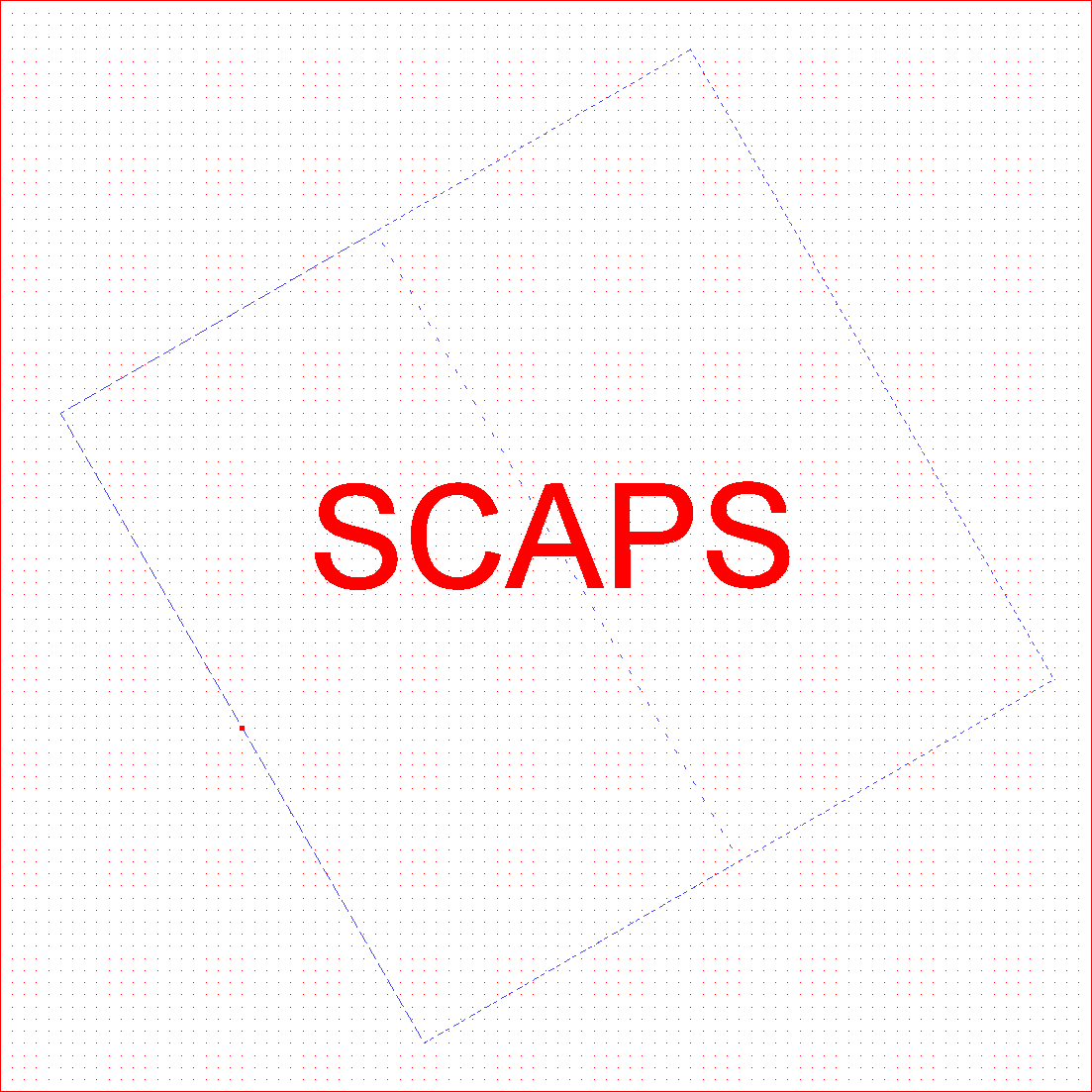
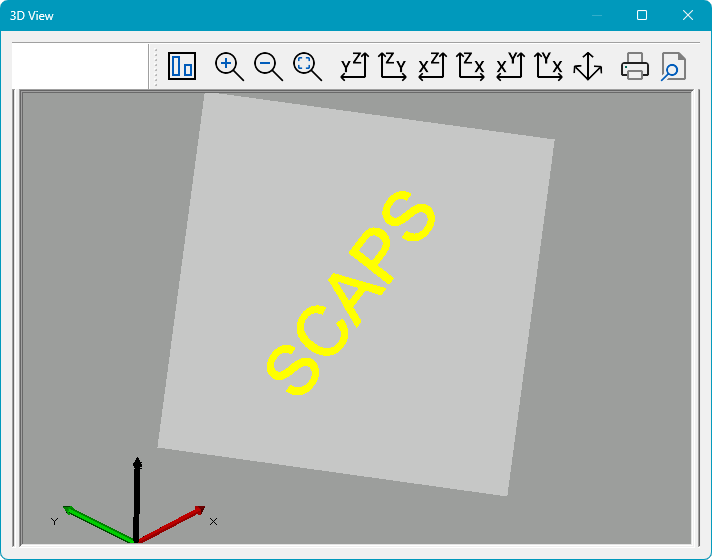
Please see below an example of a mapped text entity in the View2D (left) and 3D View (right). Please note that the 3D View can be activated by clicking on the icon  in the toolbar.
In the View2D, the bigger dashed rectangle represents the projection of the surface onto the XY plane. The inner dashed rectangle represents the actual dimensions of the surface in 3D space as viewed along the Z axis (top view).
Figure 503: 3D Tilted Surface in View2D |
Figure 504: Tilted Surface in 3D View |
|
For optimal marking quality, keep the marking area centered beneath the laser. Moving it too far away from the center reduces the laser incidence angle and may result in lower marking quality. |
|---|
|
Please note that points and point clouds are not visible in the 3D preview. |
|---|