|
<< Click to Display Table of Contents > Transformations |
  
|
|
<< Click to Display Table of Contents > Transformations |
|
Translation, Scaling, Rotation and Shearing can be applied to any geometric object. If the Optic3D option is available, 3D Transformations are also available.
For transformations performed with the mouse, refer to View2D → Manipulation of Objects.
Transformations Using the Keyboard:
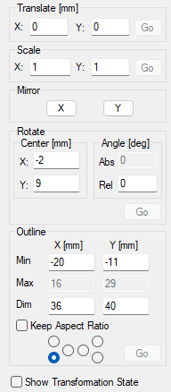
The Dimension property page is used to modify the size and position of the selected object. This page does not contain an Apply button. Instead, each transformation is executed individually by entering the desired values and clicking the corresponding Go button.
Figure 364: 2D Dimension Page |
Translate: Moves the selected object in X or Y direction relative to its current position. Scale: Changes the size of the selected object relative to its current dimensions. X scales in horizontal direction, Y scales in vertical direction. Rotate: Rotates the selected object about a specified center point. Center: Defines the center point about which the selected object is rotated. By default, the rotation center corresponds to the geometric center of the selected object. If coordinates are specified for X and Y, the rotation is performed about the defined center point. After the rotation has been executed, the object's geometric center is recalculated automatically, and the rotation center coordinates are updated to display the new geometric center. X: X coordinate of the rotation center. Y: Y coordinate of the rotation center. Angle: Defines the rotation angle in degrees. Abs: Displays the absolute rotation angle of the entity. After a rotation is executed, the relative angle is added to the current absolute angle. Multiple rotations accumulate, and the absolute angle represents the sum of all applied rotation angles. Rel: Defines the relative angle applied during the current rotation operation. After clicking Go, this value is reset to '0'. Both positive and negative values are permitted. Outline: The Outline function is used to position or resize the object's bounding rectangle. Minimum Coordinates (Min): Defines the minimum coordinates of the outline. Maximum Coordinates (Max): Defines the maximum coordinates of the outline Dimension (Dim): Defines the overall size of the outline. X defines the width and Y the height. Keep Aspect Ratio: When enabled, the width-to-height ratio remains constant during resizing operations. Radio Buttons: The radio buttons define the reference point used for outline transformations. The corresponding coordinate fields are displayed automatically depending on the selected option. |
Transformation State:
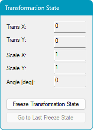
When the checkbox Show Transformation State in the 2D Dimension Page is enabled, the Transformation State dialog appears. The dialog contains the current transformation values of the selected object.
Figure 365: 2D Transformation State |
Trans X: Displays the translation in X direction. Trans Y: Displays the translation in Y direction. Scale X: Displays the scale factor in X direction. Scale Y: Displays the scale factor in Y direction. Angle: Displays the rotation angle. Freeze Transformation State: Saves the current transformation state of the selected object. The saved state can be restored later if additional modifications are made and the previous configuration needs to be recovered. Go to Last Freeze State: Restores the transformation state most recently saved using Freeze Transformation State. This function provides a quick method for returning to a previously stored configuration. |
|---|