|
<< Click to Display Table of Contents > Stepper - 10 pin |
  
|
|
<< Click to Display Table of Contents > Stepper - 10 pin |
|
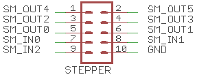
The Stepper connector provides three TTL level inputs and six TTL level outputs. All levels are defined in respect to GND. The pin assignment is shown in figure below.
Type |
Name |
Pin number |
|
Figure Figure 10: STEPPER Connector Assignment |
|---|---|---|---|---|
Output |
Stepper_Out_0 |
pin 5 |
||
Stepper_Out_1 |
pin 6 |
|||
Stepper_Out_2 |
pin 3 |
|||
Stepper_Out_3 |
pin 4 |
|||
Stepper_Out_4 |
pin 1 |
|||
Stepper_Out_5 |
pin 2 |
|||
Input |
Stepper_In_0 |
pin 7 |
||
Stepper_In_1 |
pin 8 |
|||
Stepper_In_2 |
pin 9 |
|||
Ground |
GND |
pin 10 |
Table 17: Stepper - 10 Pin Assignment
The USC card has 3 TTL stepper inputs Stepper_In_0..2 and 6 TTL stepper outputs Stepper_Out_0..5 on the Stepper - 10 pin connector.
Unlike the Opto I/Os, Laser_Gate, Laser_A and Laser_B the Stepper I/Os are not optical isolated from the USC main power circuit.
Stepper_In input levels: •The voltage on Stepper_In_0..2 may not exceed +24 V in respect to GND. Above 5 V a suitable external series resistor is required. •The input level of Stepper_In signals in respect to GND: olow: between 0 V and UTh - 1 V ohigh: between UTh + 1 V and 24 V ▪By default, the input threshold for activation of Stepper_Ins UTh is around 2.0 V. This threshold can be increased by the use of an appropriate external resistor RExt must be added. Calculate the value of the resistor with the following formula:
Stepper_Out output levels: •The output levels and max. currents are listed in chapter Electrical Characteristics.
|