|
<< Click to Display Table of Contents > Opto_Ins |
  
|
|
<< Click to Display Table of Contents > Opto_Ins |
|
Possibilities of use: •The first two inputs are predefined and cannot be used for any other purpose. The polarity of both inputs is active high and cannot be inverted. oThe Opto_In_0 (Trigger Start) is used to start jobs in trigger mode. A rising edge on this input starts the marking process if the USC card is waiting for an external start. Software jitter is avoided by using the trigger mode. oThe Opto_In_1 (External Stop) is used to stop all output processes of the USC card. A high signal on this input stops the currently running process and all further marking processes. It takes up to 150 µs after rising edge until the laser signals are switched off. •The other four Opto_Ins (Opto_In_2..5) can be used for various things like ScWaitForInput control objects, message inputs, JobIOSelection inputs, motion controller reference inputs, short key inputs, pause control input, shutter feedback, etc. •The USC-card does check every 10µs for the status of the OPTO_Ins. Input levels: •The Opto_Ins do not require the Opto_VCC supply. •The voltage on Opto_In_0..5 may not exceed +24 V in respect to Opto_GND. •The input states of Opto_In in respect to Opto_GND
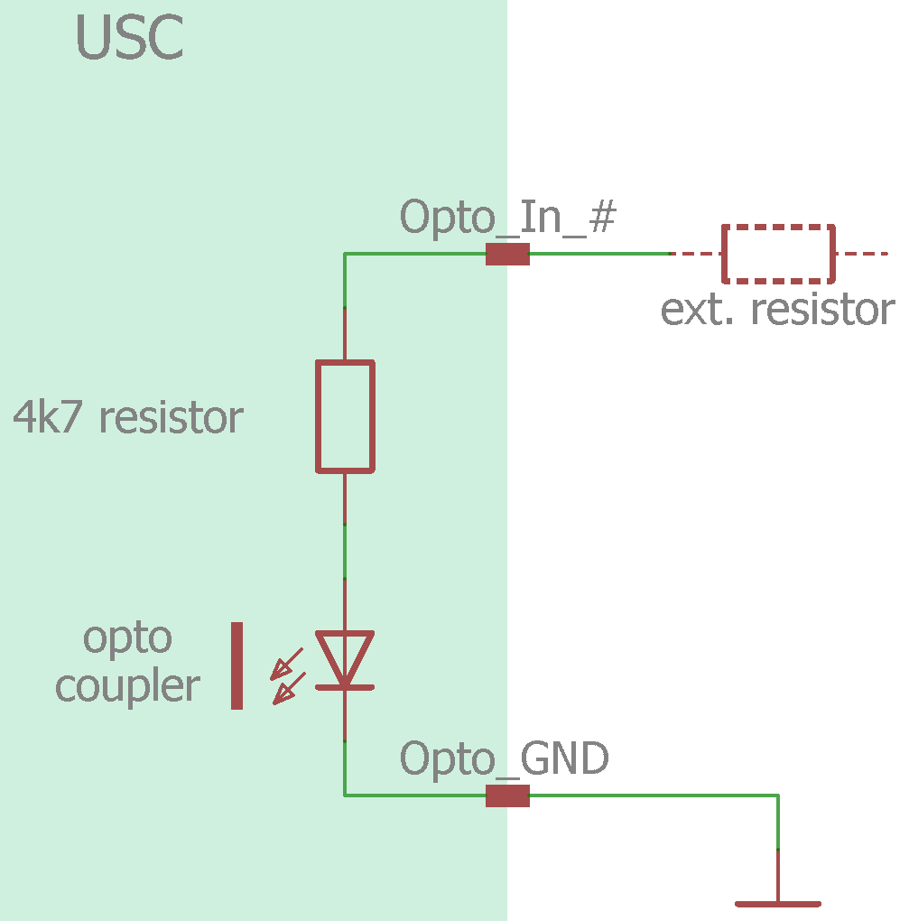
By default, the input threshold for activation of the Opto_Ins UTh is around 2.4 V. This threshold can be increased by the use of an appropriate external resistor RExt. Calculate the value of the resistor with the following formula:
Figure 21: Circuit diagram of an Opto_In with an optional series resistor Polarity: •By default the Opto_Ins are active high. •Opto_In_0 (Trigger Start) and Opto_In_1 (External Stop) cannot be inverted. •Inversions of Opto_Ins can be set in the USC-2 settings and must be saved by the store button to the card. •Temporary inversions of Opto_Ins can be done by FCI command OIUI. Check values: •CCI commands to Get Inputs •FCI command OIU •USC Server > InfoView > Inputs and InputInvertFlags |