|
<< Click to Display Table of Contents > RS-232 |
  
|
|
<< Click to Display Table of Contents > RS-232 |
|
The RxD (card output) and TxD (card input) lines are defined in respect to the connected device. So the USC-3 RxD pin should be connected to the device RxD pin and the same for the TxD pins. The baud rate can be defined between 2400 and 115200.
|
The Tx and Rx pins are already crossed internally on the USC board. Connect RxD to RxD and TxD to TxD. |
|---|
The RS-232 default settings are:
Description |
Default value |
|---|---|
DataLength |
8 |
Stop Bits |
1 |
Parity |
none |
Baud rate |
115200 |
Flow control |
none |
Table 30: RS-232 default settings
Available baud rates are 2400, 4800, 9600, 19200, 38400, 57600 and 115200. It can be changed with the SBR command.
The USC-3 gets the RS-232 commands over the 37-pin connector. The pin 32 (RS-232_Out) should be connected to the device RxD pin and the pin 33 (RS-232_In) should be connected to the TxD pin of the device. A typical connection between a standard 9-pin RS-232 connector like used with a PC is shown below.
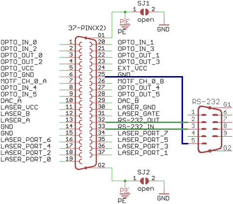
Figure 20: RS-232 pin assignment for a 1:1 cable (not crossed)
