|
<< Click to Display Table of Contents > Head3 |
  
|
|
<< Click to Display Table of Contents > Head3 |
|
Using the option Head3, it is possible to control three 2-axis scan systems with one USC-3 at the same time. Therefore an extra board called "SEB - Scan head Extension Board" and the corresponding software option is needed. Every scan head uses its own correction file and head matrix with gain, offset and rotation. The positioning signals to each scan head are updated every 30 μs.
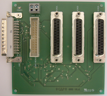
Figure 19: SEB V1.1 - Scan head Extension Board
As shown in the picture above, the board contains apart from a LED indicator for the 5 V power supply the following connectors:
Name |
Function |
Type |
|---|---|---|
USC |
Input from USC-3 X3 connector |
25 pin D-Sub (m) |
USC-HEAD2 |
Input from USC-3 HEAD2 connector |
ML 26 |
HEAD1 |
Output for first scan head |
25 pin D-Sub (f) |
HEAD2 |
Output for second scan head |
25 pin D-Sub (f) |
HEAD3 |
Output for third scan head |
25 pin D-Sub (f) |
GND 5 V |
5 V supply input for the SEB |
Screw clamp |
Table 29: Connectors of the SEB V1.1
|
The outputs provide the standard XY2-100 interface with X- and Y-channel without Z-channel and the status wire. For further information please contact SCAPS. |
|---|
