|
<< Click to Display Table of Contents > Opto_Outs |
  
|
|
<< Click to Display Table of Contents > Opto_Outs |
|
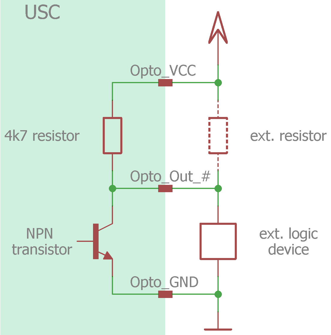
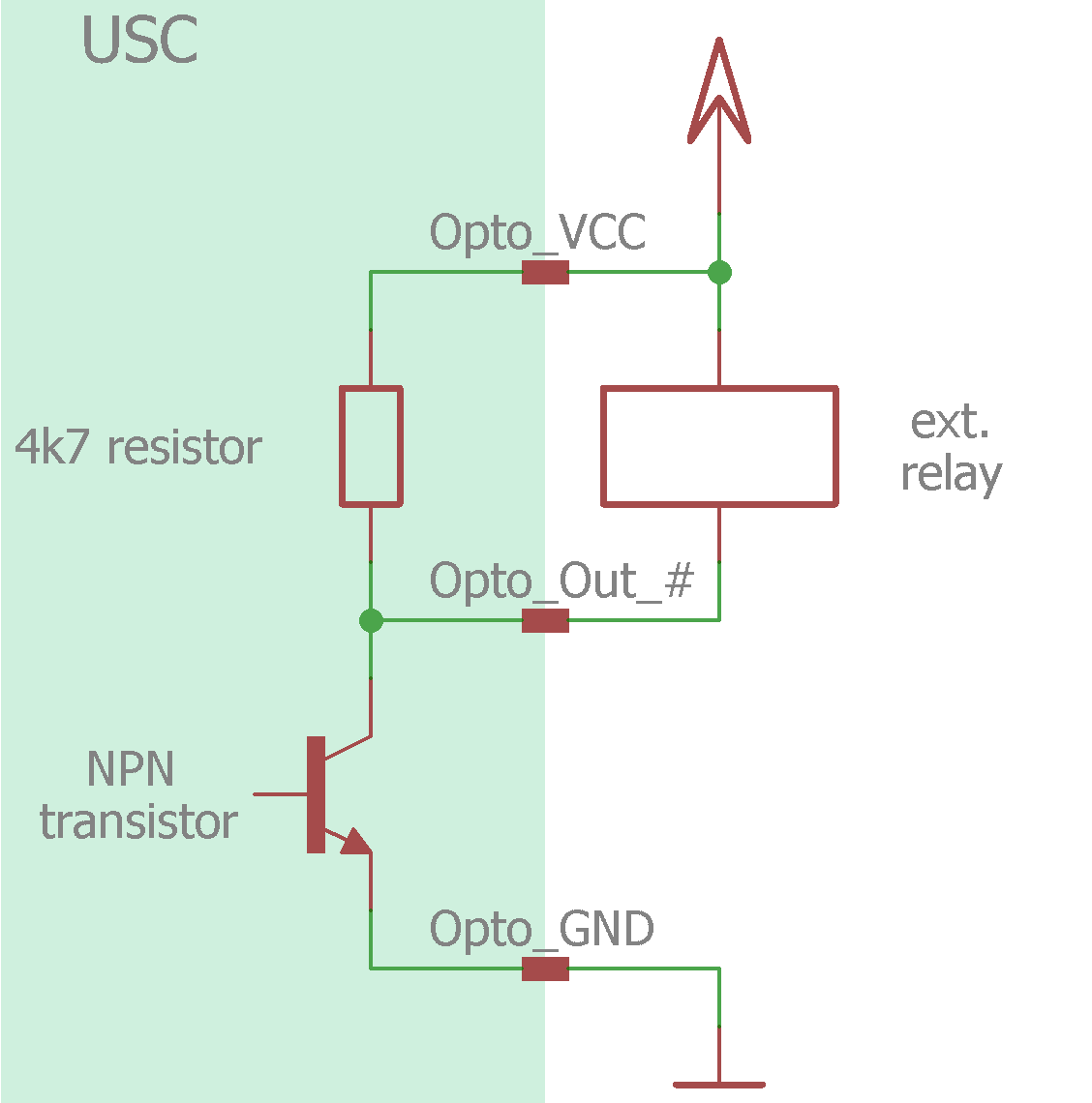
Possibilities of use: •Opto_Out_0 is predefined and cannot be used for any other purpose. It indicates marking in process (MIP) of the USC-1 and corresponds to the red LED. •Opto_Out_2 is semi predefined. It is mainly used to control a red pointer. •The other four Opto_Outs (Opto_Out_1 and Opto_Out_3..5) can be used for various things like ScSetOutput control objects, status outputs, motion controller step and direction, shutter control, etc.
Output levels and max. current: •To use the Opto_Out signals, a suitable power supply has to be connected to Opto_VCC and Opto_GND. •All Opto_Outs are open-collector outputs with an internal pull-up resistor of 4700 Ω on a common anode. This means that the individual outputs cannot be operated with different voltages. •The output levels and max. currents of the Opto_Outs depend on the circuit. The values are listed in chapter Electrical Characteristics. Ext. resistor: •In logic circuit a suitable external pull-up resistor can be used to decrease signal rising edge. The values are listed in chapter Electrical Characteristics. In most cases a resistor between 470 Ω and 4700 Ω is a good choice. •Furthermore, the external resistor provides higher currents in the closed logic circuit. But if more power is needed, the relay circuit is recommended. Polarity: •By default, the polarity of Opto_Outs is active low. •All Opto_Outs can be inverted with InvertOptoOut in sc_usc.cfg. Boot state: •The boot state of Opto_Outs is inactive. Check values: •CCI commands to Get Outputs and Set Outputs |