|
<< Click to Display Table of Contents > Z Lookup Table Calibration |
  
|
|
<< Click to Display Table of Contents > Z Lookup Table Calibration |
|
|
Before starting with the calibration of the 3D system, the optic system needs to be well-calibrated in 2D. Then, the calibration of the 3D optic system (lookup table in SAMLight) is done with the following steps (see figure 85 for an overview): |
|---|
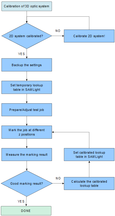
Figure 85: Overview of calibration process.
1. Set up of the temporary lookup table |
|---|
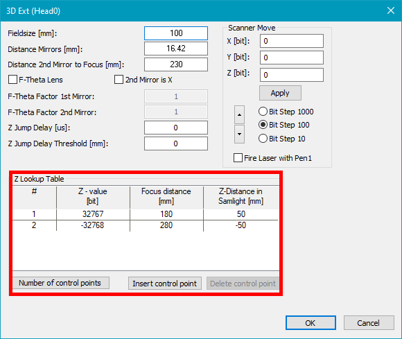
Figure 86: Z-Correction Settings |
•Set field size [mm]: Use the same value as in Settings → System → Optic → Lens → Size. (Set X gain to 1 and Y gain to 1). •Set Distance mirrors [mm]: This value of the distance between the x and y mirror is given by the scan head manufacturer or can be estimated. •Set Distance 2nd mirror to focus [mm]: This value defines the focus distance for SAMLight Z=0mm. This value has to be inside the Focus distance [mm] range of the Z lookup table (see figure 87). Please note that this distance is NOT the distance between the focus and the case of the scan head but between the focus and the position of the 2nd mirror inside the box of the scan head. •Enable F-Theta lens if an F-Theta lens is used. •Set up a temporary linear Z lookup table. Make sure, the value of Distance 2nd mirror to focus is within the lookup table. In the example given in figure 86 and below, the lookup table is set symmetrically around the Distance 2nd mirror to focus. i.Example for typical Z shifting devices: oDistance 2nd mirror to focus = 230mm o-32767bit at 190mm o0 bit at 230mm o32767bit at 270mm ii.Example for Optotune lens: oDistance 2nd mirror to focus = 230mm o20000bit at 190mm o0 bit at 230mm o-20000bit at 270mm |
|---|
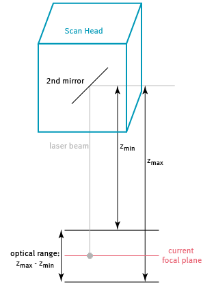
Figure 87: Illustration of optical range and distance 2nd mirror to focus.
2. Preparation and marking of the test job: |
|---|
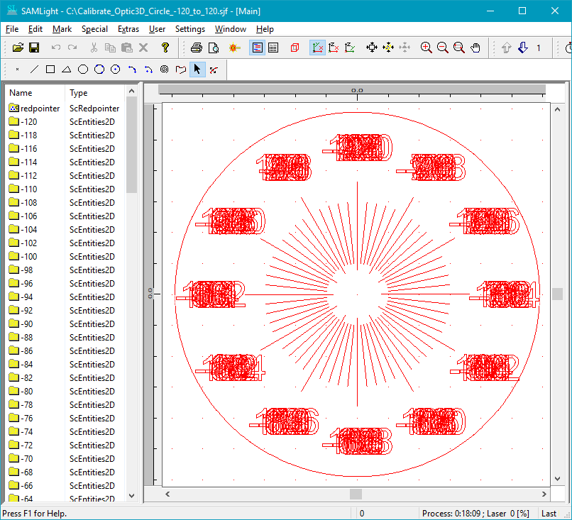
Figure 88: job file Calibrate_Optic3D_Circle_-120_to_120.sjf |
a.Load the job file Calibrate_Optic3D_Circle_-120_to_120.sjf (see figure 89). b.Remove unneeded Z values of the job: i.Delete all Z values below Distance 2nd mirror to focus [mm] minus minimum of Z lookup table Focus distance [mm]. ii.Delete all Z values above 'Distance 2nd mirror to focus [mm]' minus 'maximum of Z lookup table Focus distance [mm]'. iii.Save the reduced job with a new proper name. c.Start marking at Distance 2nd mirror to focus [mm] (for Z =0) and optimize the marking: i.Use a slow mark speed. ii.Use a slow mark speed and a high jump delay. iii.Adjust the pen power (eventually use SAMLight Parameter Finder) that you can easily define the Best marked line in the marking result. Usually, you find the Best marked line at the middle of marked scale, see figure 90. d.Mark the same job file at different Target heights which you reach for example with the mechanical z-axis (see figure 89 for illustration): i.Decrease the distance between scan head and marking target step by step. 1.Mark the job on each Target height until you are completely out of focus (no more marking result). 2.Write next to each marking result the Target height. ii.Now increase the distance between scan head and marking target step by step (start marking at Distance 2nd mirror to focus [mm] (for Z =0)). 1.Mark the job on each Target height until you are completely out of focus (no more marking result). 2.Write next to each marking result the 'Target height'. |
|---|
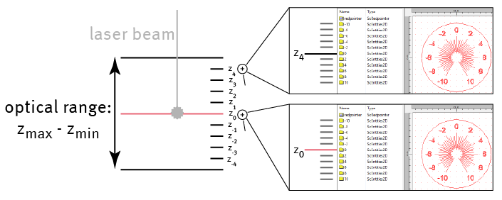
Figure 89: Illustration of the process of marking of the job at several different target heights: in this example, the z-axis is driven to the z-positions between z_4 and z_-4. At each position, the job is marked which consists of several entities at different z-positions. Examples are given for z_4 and z_0.
After step 2d) you should have marking results together with target heights similar to figure 90:
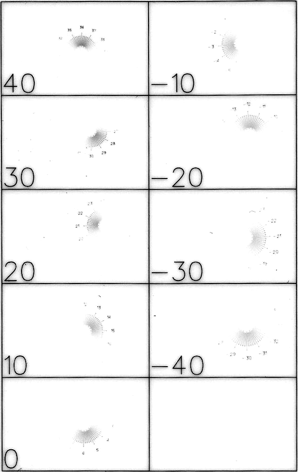
Figure 90: Marking result of job file Calibrate_Optic3D_Circle_-50_to_50.sjf
3. Analysis of the marking result with calculation of the new (calibrated) lookup table
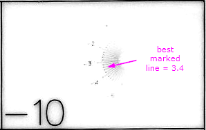
Figure 91: Example for best marked line: here at 3.4.
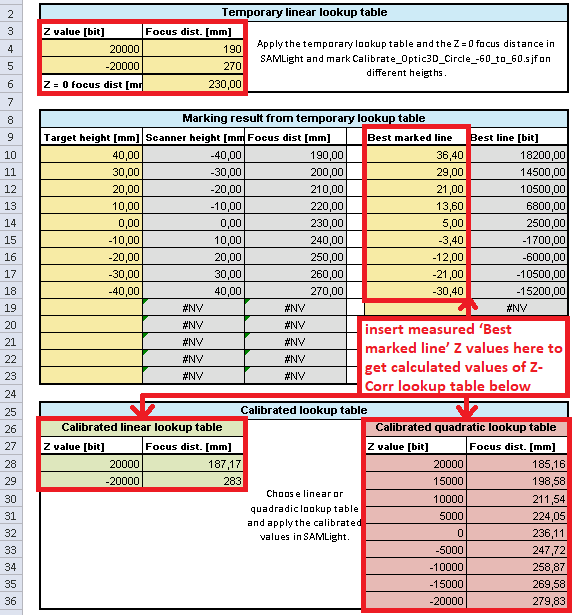
Figure 92: Get the calibrated Z lookup table with the marking results from 2. and the excel file Calibrate_Optic3D_v0.9.3.xlsx |
You can use the excel file Calibrate_Optic3D_v0.9.3.xlsx which you need to adjust according to your temporary lookup table and your measurement. Delete all lines that you did not use in your measurement. a.Temporary linear lookup table: Insert the values of your temporary linear Z lookup table and Distance 2nd mirror to focus (Z = 0 focus dist) to the excel file (see figure 94) b.Marking result from temporary lookup table: Insert the values of Scanner height and of the Best marked line for all valid marked target heights. The Best marked line must be read out from the marking result. The marking result consists of several lines corresponding to different z-values. Look for the line which is best in focus, meaning sharply marked and in the middle of the marked lines. Towards the edges, the lines should become less sharp and lighter. See figure 93 for illustration. Skip Best marked line values, which are very close to the limits of the Z range of the temporary linear lookup table. c.Calibrated lookup table with linear and quadratic fit details. In the excel file, there is a graphic representation of the data. In this plot, you can check your data for inconsistencies like measurement errors. Decide if you want to use the linear fit or the quadratic fit. |
|---|
4. Adaption of the lookup table in SAMLight
Insert the values of the calibrated lookup table (linear or quadratic, from figure 92 Calibrated lookup table) to SAMLight. To do so, click on the button Change count of Z-Corr lookup control points and define the total number of control points. Then, fill the lookup table with the values from your excel file. Leave the dialog with OK.
|
It could be that your system does not need the full defined bit range from the temporary linear Z lookup table to reach the limit in z-range. Remember that you can only set points in the lookup table that are shifted maximum +/- FS/2 relative to the defined zero point in SAMLight. If you try to set the full calibrated linear/quadratic lookup table in SAMLight, you will get the error message telling that you are out of z limit. Use the linear/quadratic fit function and use the theoretical focus distance limits from the temporary linear Z lookup table to calculate the bit value for the calibrated lookup table. Now you have the limits. If you use the quadratic fit, then remove all calculated points that are located outside your calculated limits. |
|---|
5. Marking of the test job using the calibrated lookup table
a.Use your job file (modification of Calibrate_Optic3D_Circle_-120_to_120.sjf) and mark this job again at different Target heights (in reality) just as you have been doing in 2.
b.The Z lookup table is optimal, when the Target height and the Best marked line are identical.
Target height = Distance 2nd mirror to focus [mm] (for Z =0) minus distance between scan head and marking target
Note: Mind the sign! A distance between scan head and marking target greater than Distance 2nd mirror to focus [mm] can be related to a negative Target height depending on the Z-axis orientation in SAMLight.
6. After the Z lookup table calibration process, it is possible to redefine the distance between scan head and marking target for SAMLight Z=0 by adjusting Distance 2nd mirror to focus [mm]. The Z lookup table remains calibrated.
|
Please note that the z-range is limited by the value of the field size (FS): starting with Z=0 (position of 'Distance 2nd mirror to focus [mm]', the reachable range is +/- FS/2. |
|---|