|
<< Click to Display Table of Contents > Slicing |
  
|
|
<< Click to Display Table of Contents > Slicing |
|
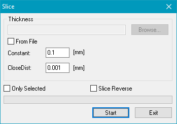
Before you can mark a 3D object, it has to be sliced. This means, it has to be separated into many 2D layers, which then can be marked as normal 2D objects. After marking a layer, a motor has to move the target object to the next z-position or the z-focus of the scan head has to be set to the next z-position. You can choose between these two options by checking or unchecking Menu bar → Settings → System → 3D → Use Optical Z-Axis. To slice the object choose Menu bar → Edit → Slice. The following dialog appears:
|
Constant: Determines the distant between two successive layers. CloseDis: If the distance between two polylines is smaller than this value, they will be closed automatically. With "0", the functionality is disabled. Only Selected: Only selected objects will be sliced. |
Slice Reverse:
The default slice order is from the bottom to the top along the z-axis in positive direction. By activating this option the slice order is reversed. This will also reverse the order for marking. One possible application would be "Deep Engraving". Reverse slicing is currently only useful for single objects, multiple objects with identical Z-ranges or multiple objects with Z-ranges that do not overlap.
From File: The slicing information can be read from a file, too. This file is a plain *.txt file with the following structure:
2
number of slices
[R]
target_dist;step_width pen_number [hatch_number]
target_dist pen_number [hatch_number]
Here the 2 is a version number that corresponds to the internal structure of the file. This field is mandatory. The next line contains a number that is equal to the number of slices that have to be created for that file. This number is used for internal calculations and to provide an expressive progress bar. The third line specifies if all following target_dist parameters are relative to the base of the mesh (R set) or if the target_dist specifies absolute values in the used coordinate system (empty line without R).
All following lines describe the slices itself. Here two methods are possible. The first one describes a target_dist and a step_width. Here the step_width is used for the thickness of all slices until the specified target distance is reached. Using this syntax it is possible to define a range of slices just by using one single line. The second syntax provides the possibility to define one single slice. Here the target_dist specifies where this single slice has to end. Both methods of defining slices use the preceding slice position as starting point. The thickness of a slice results out of the difference between both values. Additionally a pen number is specified in both cases. This one-based pen number is assigned to the related slices. And as a third, optional parameter, the number of the hatch that has to be applied to that slice can specified. It corresponds to the default hatch styles of the hatch property pane. To use such a predefined hatch, here the required parameters have to be stored and the related hatch 1 and/or 2 has to be enabled.
As an example such a slice definition file can look like this:
2
13
R
0.10;0.01 1
0.11 2
0.15 1
0.17 3
Here the file version number is 2 is used, to exactly specify this format. The number of slices defined within that file is 13 and all given distances are relative to the starting coordinate of the 3D mesh. First there is a range of slices defined. Here, ten slices have to be created from position 0.00 to position 0.10 with a thickness of 0.01. Pen 1 is assigned to all ten slices. Subsequently, these three slices are created:
•a single slice from 0.10 to 0.11 (= thickness of 0.01), with pen 2 assigned
•a single slice from 0.11 to 0.15 (= thickness of 0.04), with pen 1 assigned
•a single slice from 0.15 to 0.17 (= thickness of 0.02), with pen 3 assigned
Reverse Slicing direction: If you want to reverse the direction of the slicing from bottom to top to top to bottom write R;S in the second line of the file. The Slice Reverse checkbox must NOT be activated.
Constant: Choose the distance between two successive layers in [mm].
Start: Start slicing and create a new entity which holds the sliced layers.
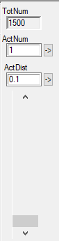
Once the object has been sliced, a new entity is shown in the entity list, and on the right hand of the main window a slice control becomes active:
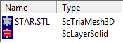
The entity which holds the sliced layers is of the type ScLayerSolid. The entity which holds the original information of the 3D object is of the type ScTrialMesh3D.
|
The Slice Control allows to access the slices and get information about them. TotNum: The total number of the slices. ActNum: The number of the currently selected slice. You can enter the number of a slice and jump to it by pressing the arrow button. ActDist: The z-distance from the ground of the currently selected slice. You can enter a distance and jump to it by pressing the arrow button. Scroll bar: Click on the bar and move the mouse up or down to select a slice. The currently selected slice will also be shown in the View 3D as a green contour which indicates the layer. |
|---|
|
Slicing an entity more than once will lead to a corresponding number of sets of layers (ScLayerSolid entities).The slice distances may vary. |
|---|
|
During slicing, polylines are generated. Depending on the orientation of the polylines, the lines will be displayed in different colors: inner polylines (orientation counter-clockwise) are displayed in red, outer polylines (orientation clockwise) are displayed in green. The orientation is important for hatching, especially in combination with a beamcompensation. A mixture of inner and outer polylines will lead to a different beamcompensation. If unwanted, the Improved Beam Compensation could help. |
|---|
|
While creating an entity of the type ScLayerSolid or loading a *.s3d file containing such one, a set of temporary files with name ddds3dHHH(H).tmp -and since SCAPS installer 4.0.5.0006 s3dHHH(H).tmp, with H being hexadecimal numerals- are generated at <SCAPS>\intermed folder to fluently handle the potential big amount of slicing data. These temporary files are deleted when all entities of the type ScLayerSolid are deleted, or the job or SAM3D are closed. |
|---|