|
<< Click to Display Table of Contents > Gain of Optic Settings |
  
|
|
<< Click to Display Table of Contents > Gain of Optic Settings |
|
Optic settings allow to set a gain value for the x and y coordinates. These gain values are thought to compensate slightly optic distortions to archive a quadratic field. Values less than 1 will reduce the scanner field. Values greater than 1 will expand the scanner field.
In the following, two figures are given to illustrate the effect of different field sizes for a given optical field as well as different gain values for a given field size and given optical field.
In figure 501, the effect of different field sizes for a given optical field (of 100mm) is shown:
a) If the correct field size is used in SAMLight (FS = 100 mm), the marking results will be of the identical size as given in SAMLight.
•The left hand side shows the View2D in SAMLight with a circle of 30 mm diameter in black and a rectangle covering the full field of 100 mm x 100 mm in red.
•In the middle, the calculation of the SAMLight mm into bit (sent to the scan head) is done. In addition, the calculated bit value is used to calculate the size of the marking result which depends on the size of the optical field - a physical property of the scan head.
•On the right hand side, the marking result as given by the scan head is shown. In this example a), the circle is marked with 30 mm diameter and the rectangle with 100 mm side length.
b) If the defined field size used in SAMLight is too small (FS = 50 mm), the marking results will be too big compared to the values in SAMLight.
•The left hand side shows the View2D in SAMLight with a circle of 30 mm diameter in black and a rectangle covering the full field of 50 mm x 50 mm in red.
•In the middle, the calculation of the SAMLight mm into bit (sent to the scan head) is done. In addition, the calculated bit value is used to calculate the size of the marking result which depends on the size of the optical field - a physical property of the scan head.
•On the right hand side, the marking result as given by the scan head is shown. In this example b), the circle is marked with 60 mm diameter because of the wrongly set field size. The rectangle is marked with 100 mm side length again covering the full field.
c) If the defined field size used in SAMLight is too big (FS = 150 mm), the marking results will be too small compared to the values in SAMLight.
•The left hand side shows the View2D in SAMLight with a circle of 30 mm diameter in black and a rectangle covering the full field of 150 mm x 150 mm in red.
•In the middle, the calculation of the SAMLight mm into bit (sent to the scan head) is done. In addition, the calculated bit value is used to calculate the size of the marking result which depends on the size of the optical field - a physical property of the scan head.
•On the right hand side, the marking result as given by the scan head is shown. In this example c), the circle is marked with 20 mm diameter because of the wrongly set field size. The rectangle is marked with 100 mm side length again covering the full field.
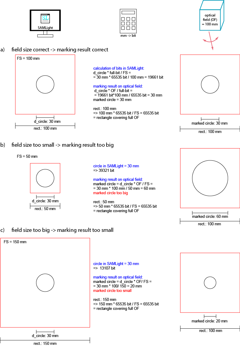
Figure 501: Different field sizes with same optical field will result in wrong marking sizes.
In figure 502, the effect of different gain values in x for a wrongly set field size (150 mm) and a given optical field (of 100mm) is shown:
a) If the wrong field size is used in SAMLight (FS = 150 mm) in combination with a wrong gain in x (= 0.667) while using neutral gain in y (= 1), the marking result will be wrong in x as well as in y direction compared to the values given in SAMLight.
•The left hand side shows the View2D in SAMLight with a circle of 30 mm diameter in black and a rectangle covering the full field of 150 mm x 150 mm in red.
•In the middle, the calculation of the SAMLight mm into bit (sent to the scan head) is done taking into account the non-neutral gain in x direction. In addition, the calculated bit value is used to calculate the size of the marking result which depends on the size of the optical field - a physical property of the scan head.
•On the right hand side, the marking result as given by the scan head is shown. In this example a), the circle is no longer a circle due to the different gains in x and y: it is marked with 20 mm diameter in y and 13.3 mm in x direction. The rectangle is marked with 100 mm side length in y direction where the neutral gain of 1 is used. In x direction however, the rectangle is compressed to 66.7 mm due to the combination of the field size 150 mm and the gain in x 0.667.
b) If the wrong field size is used in SAMLight (FS = 150 mm) in combination with a correct gain in x (= 1.5) compensating the field size in respect to the optical field (while using neutral gain in y (= 1)), the marking result will be correct in x and still be wrong in y direction compared to the values given in SAMLight.
•The left hand side shows the View2D in SAMLight with a circle of 30 mm diameter in black and a rectangle covering the full field of 150 mm x 150 mm in red.
•In the middle, the calculation of the SAMLight mm into bit (sent to the scan head) is done taking into account the non-neutral gain in x direction. In addition, the calculated bit value is used to calculate the size of the marking result which depends on the size of the optical field - a physical property of the scan head.
•On the right hand side, the marking result as given by the scan head is shown. In this example b), the circle is no longer a circle due to the different gains in x and y: it is marked with 20 mm diameter in y and 30 mm in x direction. The rectangle is marked with 100 mm side length in y direction where the neutral gain of 1 is used. In x direction however, the rectangle is truncated to 100 mm due to the combination of the field size 150 mm and the gain in x 1.5 which results in a side length of 98303 bit much bigger than the maximum bit range of 65535 bit. This means that everything outside of the green lines in the View2D (left hand side of the figure) will be mapped to the maximum bit value of 65535 bit. In this case, SAMLight will also show a message to inform about the data out of range. In addition, the marking speed given in the used pen in SAMLight will no longer be correct.
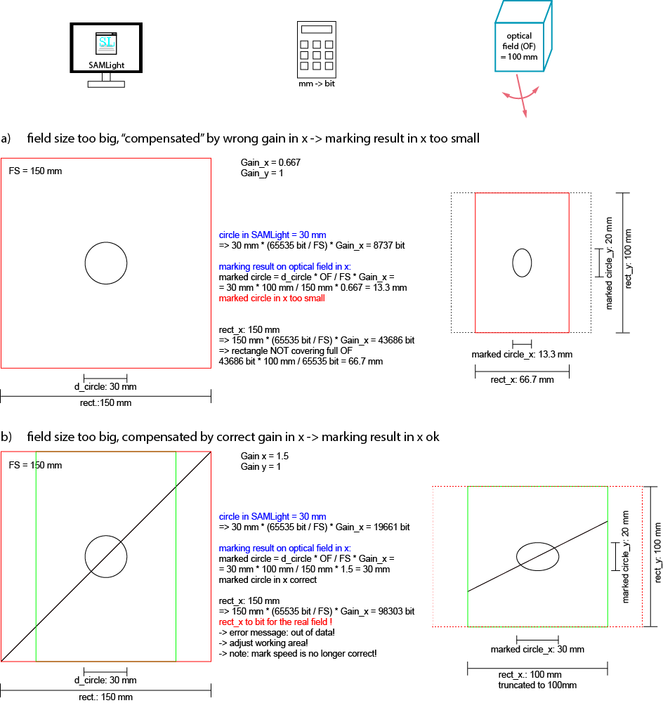
Figure 502: Marking result of different gain values with same field size and same optical field.
|
We strongly recommend to adjust the field size in SAMLight as accurate as possible and just use a gain for fine tuning if necessary. Please find further information in the chapter on calibration.
|
|---|
