|
<< Click to Display Table of Contents > Loop OptoOut to OptoIn |
  
|
|
<< Click to Display Table of Contents > Loop OptoOut to OptoIn |
|
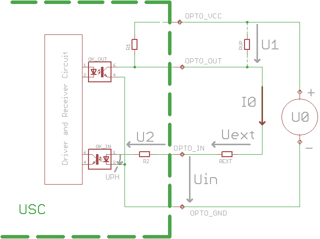
Figure 37: Loop OptoOut to OptoIn
In the case when the transistor of OK_OUT (nodes 4 & 6) is switched off because the photo diode of OK_OUT (nodes 1 & 2) is off since USC port is set to logical ‚0‘ (no inversion flag set):
![]()
![]()
![]()
![]()
![]() is typically 1.2 V
is typically 1.2 V
With
![]()
This could cause a problem!
Solution 1: use an external pull-up resistor with
Solution 2: use a higher supply voltage for OptoVcc with
![]()