|
<< Click to Display Table of Contents > Calibration |
  
|
|
<< Click to Display Table of Contents > Calibration |
|
A well calibrated system is the base for a precisely working marking system. This chapter describes options for the 2D and 3D calibration of scanner marking system.
Depending on the scan head, there are several possibilities:
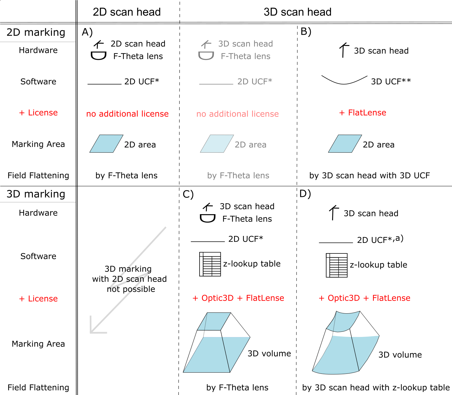
Figure 85: Calibration Options
A) "2D F-Theta" setup: For calibration, an F-Theta lens and a 2D UCF* (USC Calibration File) are needed. The field flattening for the 2D marking area is done by F-Theta lens.
B ) "FlatLense" setup: For calibration, the FlatLense license (in order to access the z-axis) is required and a 3D UCF**. The field flattening for the 2D marking area is done by the 3D scan head with a 3D UCF.
C) "3D F-Theta" setup: For calibration, the Optic3D license, the FlatLense license, a 2D UCF* and additionally a z-lookup table is needed for calibration. The field flattening for the 3D marking volume is done by F-Theta lens.
D) "3D without F-Theta lens" setup: For calibration, the Optic3D license, the FlatLense license, a 2D or 3D UCF*,a) and a z-lookup table is needed for calibration. The field flattening for the 3D marking volume is done by the 3D scan head in combination with the z-lookup table. Marking at the maximum focus length is not possible, as reserves are required for field flattening.
The greyed out option is technically valid, but not recommended.
* The 2D UCF can be acquired from the scan head manufacturer or created / edited with the correction file tool <SCAPS>\tools\sc_corr_table.
** The 3D UCF can be acquired from the scan head manufacturer. It is also possible to generate a 3D correction file with the correction file tool <SCAPS>\tools\sc_corr_table, but a 3D calibration with z-lookup table is necessary first.
a) A 3D UDF can also be used, but SAMLight will ignore the z-values from the UCF file and use the z-values from the z-lookup table instead.