|
<< Click to Display Table of Contents > Optic3D USC |
  
|
|
<< Click to Display Table of Contents > Optic3D USC |
|
Requirements: for USC-1, USC-2 and USC-3 cards
Correction File:
2D .ucf correction file provided by SCAPS
Required SCAPS Option:
FlatLense
Optic3D
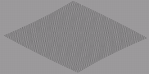
Figure 525: Shape of a 2D Correction File
Global Settings:
For USC cards, open Settings → System → Optic:
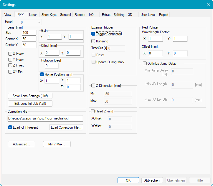
Figure 526: Global Settings Optic Dialog for Z-Dimension
In this dialog the XY field size, the correction file and the Z-dimension can be configured.
Z Dimension:
The Z Dimension settings should only be modified by users familiar with Z-axis calibration.
The Z Dimension [mm] setting defines the available Z-axis range. By default, the Z range is symmetrical around Z = 0 and Minimum/Maximum values are based on the configured field size.
When the Z Dimension is changed, the Z range can be shifted and scaled. The focus distance remains associated with the same Z-bit value, and the value
corresponds to the Focus Distance, which is equal to the Distance from the second Mirror to focus.
|
Important: If Z Dimension is enabled, the default minimum and maximum Z distances always correspond to -32768 and +32767 bits. By default, a preliminary lookup table is created. |
|---|
Z-Correction Settings:
Accessing the Dialog:
USC-1: Settings → System → Optic → Advanced → Z-Correction (Enable) → Advanced
USC-2/ USC-3: Settings → System → Optic → Advanced → Correction, Settings → Z‑Correction, Settings
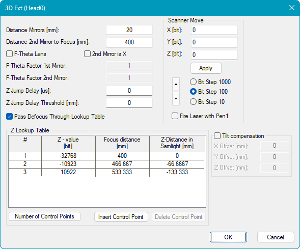
Figure 527: Z-Correction Settings
Parameter Description:
Distance mirrors: Distance between the X and Y mirrors of the scan head, specified in millimeters. This value is typically provided by the scan head manufacturer.
Distance Second Mirror to Focus: Distance between the second scanner mirror and the center of the marking field in the focal plane.
F-Theta Lens: Enable this option if an F-Theta lens is installed in addition to the third scanner axis.
2nd Mirror is X: Swaps the X an Y axes by treating the second mirror as the X mirror.
F-Theta Factor (1st Mirror / 2nd Mirror): Empirical correction factors used to compensate for the characteristics of the optical system. The calibration is described in F-theta Factor Calibration. A value of '0' represents a perfectly telecentric lens. A value of '1' represents an optical system without additional lens correction.
Z Jump Delay [µs]: Additional delay applied after large Z axis movements. Because the Z axis behaves differently from the X and Y scanner axes, additional settling time may be required after significant changes in Z position. The configured delay is added to the normal jump delay whenever the Z movement exceeds the value defined by Z Jump Delay Threshold. A value of '0' disables this feature.
Z Jump Delay Threshold [mm]: Defines the minimum Z axis movement that triggers the additional Z Jump Delay. If the Z axis distance of a jump exceeds this threshold, the configured Z Jump Delay is added to the normal jump delay.
Pass Defocus Trough Lookup Table: When enabled, defocus values are calculated using the lookup table rather then the Z field size. This option is only available for USC-3.
Z Lookup Table: The lookup table compensates for non-linear relationships between the Z axis position and the focus distance. Each table entry consists of a DAC value and the corresponding distance from the second mirror to the focus position. The entries must be ordered in ascending order by Focus Distance [mm]. This feature requires an active FlatLense license.
Number of Control Points: Defines the number of entries in the lookup table. The allowed range is 2 to 32.
Insert Control Point: Adds a new control point to the lookup table. If no row is selected, the control point is added at the end of the table. If a row is selected, the control point is inserted above the selected row.
Delete Control Point: Removes the currently selected control point from the lookup table.
|
When Z-dimension is enabled, the Minimum and Maximum Z distance values correspond to –32768 and +32767 bits. By default, a preliminary lookup table is created. |
|---|
Scanner Move: A helper function used to determine suitable lookup table values during calibration.
Step Width Settings: The Bit Step 100, Bit Step 100 and Bit Step 10 buttons define the movement increment used by the Scanner Move function.
Recommended Calibration Procedure:
i.Obtain the Correction File: Request the correction file from the scan head manufacturer and send it to: info@scaps.com. SCAPS will convert it into a UCF file without Z values.
ii.Setup the Hardware: Position the system at the intended working distance. The working distance corresponds to the Z = 0 plane.
iii.Verify the Lens Size: Determine the correct lens size value by marking a known geometry, such as a rectangle. The lens size defines how many millimeters correspond to the scanner range of 65,536 bits.
Example: 10 mm in the drawing should produce 10 mm on the workpiece at Z = 0.
iv.Determine the Mirror Distances: Determine the following mechanical parameters: Distance Mirrors (distance between the X and Y mirrors) and Distance Second Mirror to Focus (distance from the second mirror to the center of the field in the focal plane). These values are typically provided by the scan head manufacturer.
v.Enter Basic Z Calibration Parameters: Open Optic Tab of the Global Settings and enter the Field Size. Then open the Z-Correction Settings dialog and enter Distance Mirrors and Distance Second Mirror to Focus. Verify that all values correspond to the actual optical setup before proceeding.
vi.Create the Lookup Table: For best results, use a motorized Z stage to position the workpiece at known heights.
1.The valid DAC range is -32768 to +32767
2.Two approaches can be used to generate the lookup table:
a.Define DAC values and determine the corresponding focus positions
b.Define focus positions and determine the corresponding DAC values
3.Example procedure:
a.Create three control points with predefined DAC values.
b.For each DAC value, use the Scanner Move function to locate the focal position.
c.Determine the corresponding focus distances (d1, d2, d3)
d.Enter the measured focus distances into the lookup table
Additional control points can be added to compensate for non-linearities and improve calibration accuracy.
Control Point |
DAC [bits] |
[mm] |
|---|---|---|
1 |
-32768 |
d1 |
2 |
0 |
d2 |
3 |
+32767 |
d3 |
Table 66: Example Z Lookup Table for d1 < d2 < d3
Tilt Compensation: Tilt Compensation corrects small mechanical misalignment of the scan head. Compensation can be applied in X, Y and Z direction. A Z Offset value of '0' is not valid. Information on measuring the required compensation parameters can be found here.
X Offset [mm]: Enter the measured offset in the X direction offset to be compensated.
Y Offset [mm]: Enter the measured offset in the Y-direction offset to be compensated.
Z Offset [mm]: Enter the measured height difference between two Z measurement positions used to determine the tilt.
|
Please note that the Tilt Compensation is only supported for USC-3 and USC-4. |
|---|
