|
<< Click to Display Table of Contents > Board And Connectors |
  
|
|
<< Click to Display Table of Contents > Board And Connectors |
|
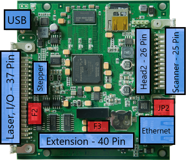
USC-3 Top View:
Figure 3: USC-3 Top View |
•USB |
|---|---|
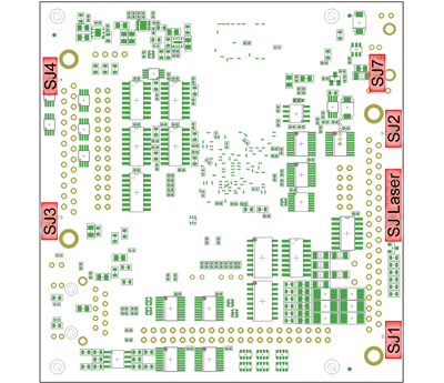
USC-3 Bottom View:
Figure 4: USC-3 Bottom View |
•Laser, I/O shield SJ1, SJ2 •Scanner shield SJ3, SJ4 •USB shield SJ7 •Laser signal solder jumpers SJ_Laser |
|
There are 4 drilled holes for mounting purposes next to the corners of the card which are not connected to anything. |
|---|