|
<< Click to Display Table of Contents > Principle Of Working |
  
|
|
<< Click to Display Table of Contents > Principle Of Working |
|
The USC-2 internal logic for decoding the encoder signals MOTF_CH_0 and MOTF_CH_1 is shown below.
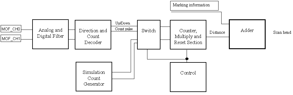
Figure 26: Principle of working
The MOTF_CH_0 and MOTF_CH_1 signals are filtered by an analog and digital filter unit. After the decoding a counter counts the incoming count pulses and is incremented or decremented according to the up and down information. In some application, the belt movement direction and speed remains constant. In this case, the count and up/down information can be generated by an internal Simulation Generator eliminating the need for an encoder. The count frequency is fixed to 100 kHz.
In order to calibrate the counter to the scanner field units [typically in bits, mm or inch] the counter value is multiplied by a user definable signed constant. The resulting distance information is added to the marking information to form the final scan head control signals.