|
<< Click to Display Table of Contents > Signals |
  
|
|
<< Click to Display Table of Contents > Signals |
|
The Flash JobIOSelect mode allows to manage the selection of jobs and the start marking event via the USC-3 I/O ports without the need of a RS-232 connection.
Flash JobIOSelect inputs |
Input pins |
|---|---|
Binary Job Selection |
Opto_In_2..5 or Digi_In_0..7 [a] |
External Trigger |
Opto_In_0 |
External Stop |
Opto_In_1 |
Table 32: USC-3 Job IO Selection inputs
[a]: The JOB_SELECT_IO_EXT flag of the FM command determines if Opto_In_2..5 (up to 15 jobs) or Digi_In_0..7 (up to 255 jobs) are used as binary job selection input pins.
Flash JobIOSelect outputs |
Output pins |
|---|---|
Mark In Progress |
Opto_Out_0 |
Ready For Trigger |
Opto_Out_3 [a] |
Job Loaded |
Opto_Out_4 [a] |
Table 33: USC-3 Job IO Selection outputs
[a]: The SYNC command allows changing the output pins for Ready For Trigger and Job Loaded.
By default, there is the timing as shown in figure below.
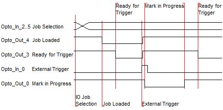
Figure 30: Job IO Selection timing diagram
The job select bits Opto_In_2 to Opto_In_5 have the following encodation:
Opto_In_2 |
Opto_In_3 |
Opto_In_4 |
Opto_In_5 |
Job number |
|---|---|---|---|---|
0 |
0 |
0 |
0 |
Empty job |
1 |
0 |
0 |
0 |
1 |
0 |
1 |
0 |
0 |
2 |
1 |
1 |
0 |
0 |
3 |
0 |
0 |
1 |
0 |
4 |
1 |
0 |
1 |
0 |
5 |
0 |
1 |
1 |
0 |
6 |
1 |
1 |
1 |
0 |
7 |
0 |
0 |
0 |
1 |
8 |
1 |
0 |
0 |
1 |
9 |
0 |
1 |
0 |
1 |
10 |
1 |
1 |
0 |
1 |
11 |
0 |
0 |
1 |
1 |
12 |
1 |
0 |
1 |
1 |
13 |
0 |
1 |
1 |
1 |
14 |
1 |
1 |
1 |
1 |
15 |
Table 34: Binary Job Selection in JobIOSelect mode
The Job selection bits must be valid during the complete mark. As soon as a new combination is applied the current running job will be interrupted and the new job - if valid - will be loaded.
Flash Job IO Select |
circuit time [µs] |
|---|---|
extern start (trigger) |
150 |
extern stop |
2000 |
Table 35: circuit time