|
<< Click to Display Table of Contents > Scanner - 25 pin |
  
|
|
<< Click to Display Table of Contents > Scanner - 25 pin |
|
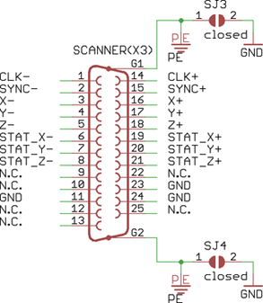
The connector X3 provides the standard XY2-100 interface. The pin assignment is shown in figure 6.
Type |
Name |
Pin number |
|
Figure 6: Scanner - 25 pin assignment |
|---|---|---|---|---|
Output |
CLK+ |
pin 14 |
||
CLK- |
pin 1 |
|||
Sync+ |
pin 15 |
|||
Sync- |
pin 2 |
|||
X+ |
pin 16 |
|||
X- |
pin 3 |
|||
Y+ |
pin 17 |
|||
Y- |
pin 4 |
|||
Z+ |
pin 18 |
|||
Z- |
pin 5 |
|||
Input |
Stat_X+ |
pin 19 |
||
Stat_X- |
pin 6 |
|||
Stat_Y+ |
pin 20 |
|||
Stat_Y- |
pin 7 |
|||
Stat_Z+ |
pin 21 |
|||
Stat_Z- |
pin 8 |
|||
Ground |
GND |
pin 11, 23, 24 |
||
Shield SJ3, SJ4 |
Solder jumper |
|||
N.C. |
N.C. |
pin 9, 10, 12, 13, 22, 25 |
Table 16: Scanner - 25 pin assignment
|
N.C.: Do not connect! Make sure that the scan head and the USC-3 have the same ground potential, to avoid damages caused by ESD. Therefore the solder jumpers SJ3 and SJ4 have to be closed (default state). |
|---|