|
<< Click to Display Table of Contents > LED Indicators |
  
|
|
<< Click to Display Table of Contents > LED Indicators |
|
The blue LED for power indication turns on with 4.2 V and switches off for power values higher than 6.2 V.
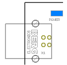
Figure 14: Power LED next to the USB port
Furthermore, there are three LED Indicators with the following function:
![]()
Figure 15: LED indicators
FPGA Access (FA, yellow):
•Indicates data transfer via the USB or Ethernet connection.
•Blinks with ~3 Hz during booting.
•Flickers during data transfer.
Mark In Progress (MIP, red):
•This LED is connected in parallel with the opto-isolated Opto_Out_0 (pin 3) output of the 37-pin connector. It is ON during marking.
Operation (OP, green):
•OFF or blinking: The device is not operational
•ON: The device is operational
For further information, see Signals During Booting.