|
<< Click to Display Table of Contents > Output Range |
  
|
|
<< Click to Display Table of Contents > Output Range |
|
The AEB-1 provides a differential output signal as shown in figure 25.
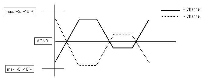
Figure 25: AEB-1 analog output
The output range can be selected for each channel separately with solder jumpers on the bottom side of the AEB-1 as shown figure 26 and described in table 13.
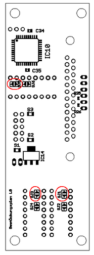
Figure 26: Solder jumpers for output range selection
Channel |
Jumper |
State |
Output range |
|---|---|---|---|
X |
SJ1 |
Open |
-10 V..+10 V |
Closed |
-5 V..+5 V |
||
Y |
SJ3 |
Open |
-10 V..+10 V |
Closed |
-5 V..+5 V |
||
Z |
SJ5 |
Open |
-10 V..+10 V |
Closed |
-5 V..+5 V |
Table 13: AEB-1 output range selection
|
By default, the 3 jumpers SJ1, SJ3 and SJ5 are closed. |
|---|
|
SJ2, JS4 and SJ6 must always remain closed. |
|---|

