|
<< Click to Display Table of Contents > Overview |
  
|
|
<< Click to Display Table of Contents > Overview |
|
The typical marking on the fly setup is shown below:
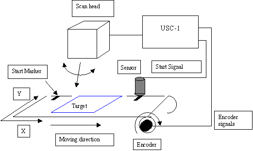
Figure 29: Marking on the fly setup
The target piece is placed on a moving belt. The movement of the belt is measured by a rotary encoder. The encoder signals are decoded by the USC-1 logic into a distance information which in turn is transferred to the Scan head to compensate the target movement. A photo sensor acts as a synchronization element by delivering a start impulse to the USC-1. This start impulse typically resets the USC-1 distance counter and initializes marking.